Design
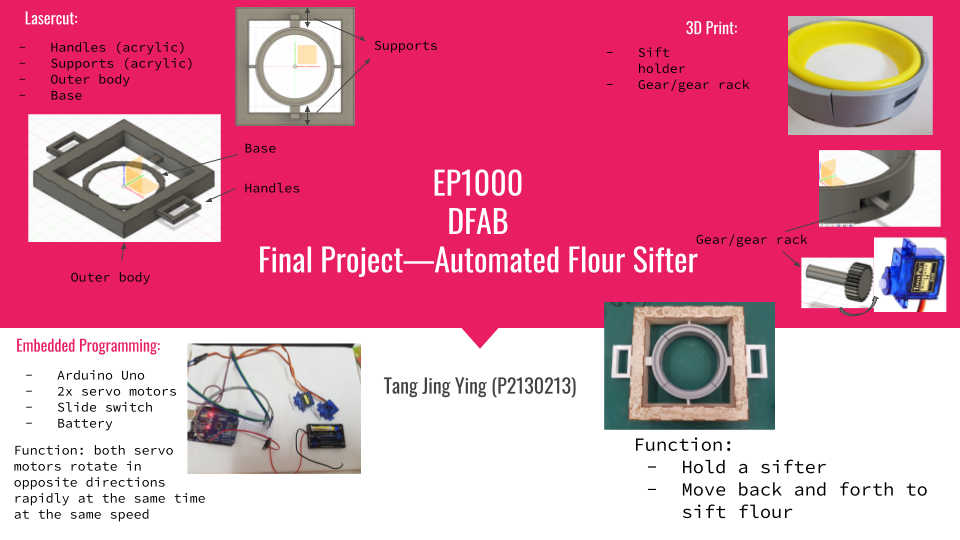
Alrighty. There's quite a lot going on here so I'm going to seperate everything into sections to make it clearer. For my final project, I am attempting to make an automatic flour sifter, because baking is a hobby I enjoy and do quite often. However, I find it frustrating and time consuming sometimes to sift the flour (it's best to sift flour to avoid lumps) so I took this opportunity to try to create a machine that will do it for me.
The design will be a body in the middle with a an open centre that holds the sift up and allows it to do its thing. There'll also be another body that would move the body in the middle back and forth in order to sift the flour. This body would include handles so I can hold it up while sifting. Let's begin.
3D Print
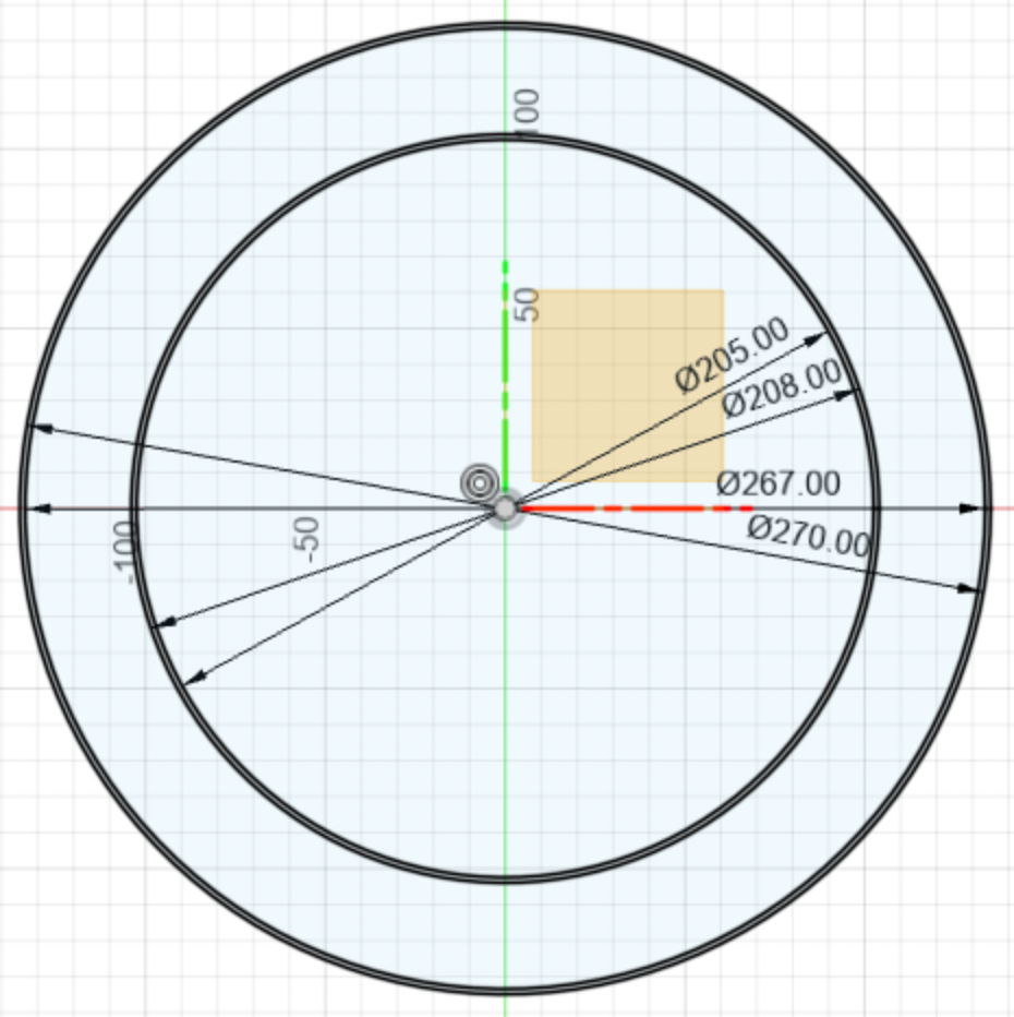
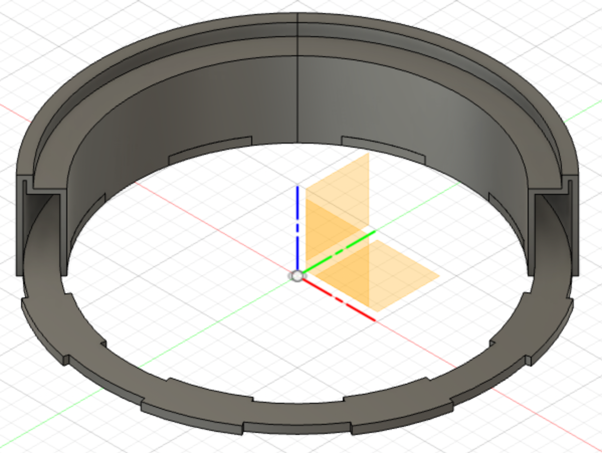
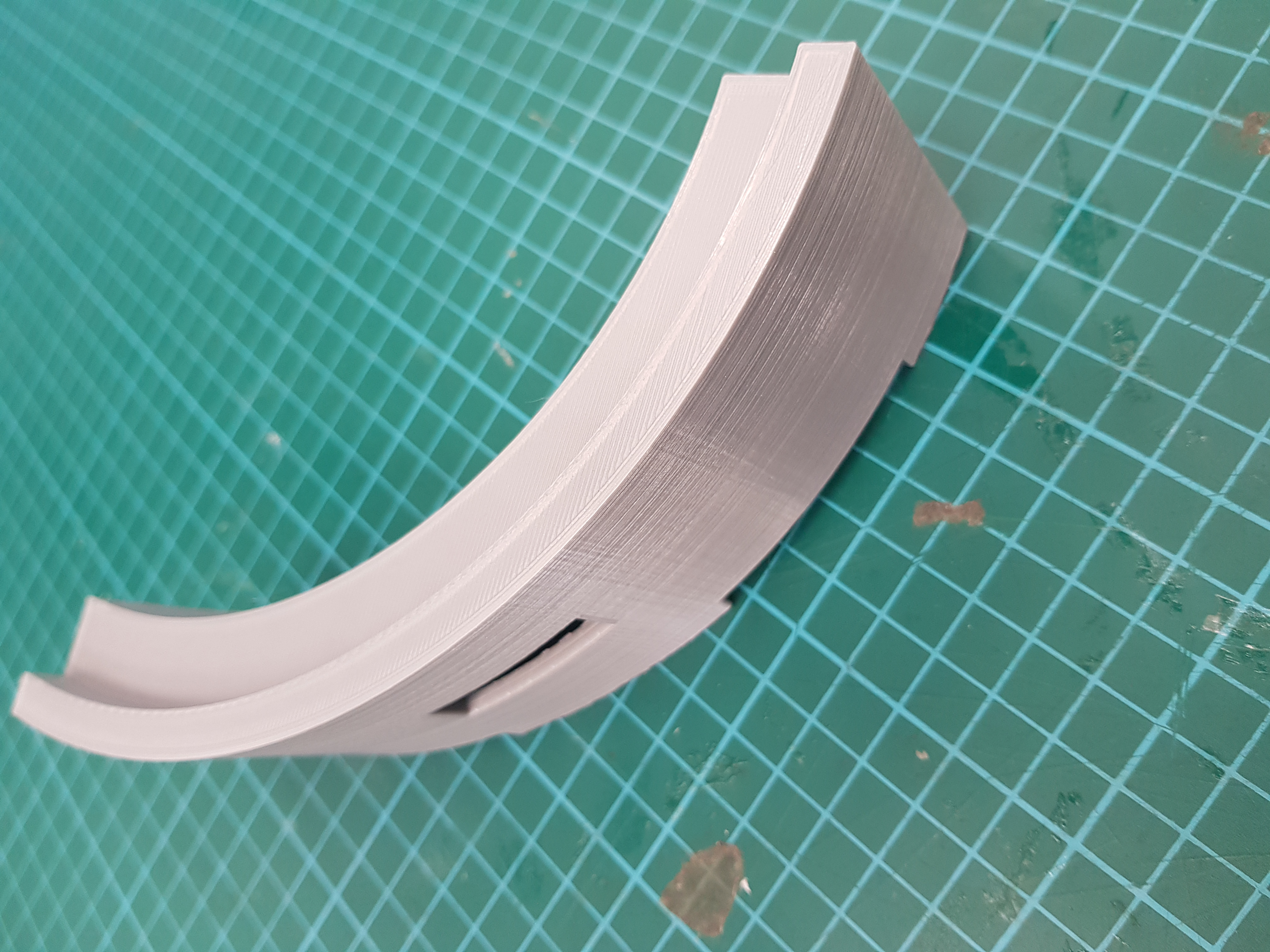
I'm going to start off by creating my 3D design. First I measured the sift I usually use, and design in according to the dimensions so that the sift can sit in the middle of the structure, and be held up by the brim. I started by creating a bunch of circles according to the dimensions to make the body. I then extruded it to 55mm for the walls of the body.
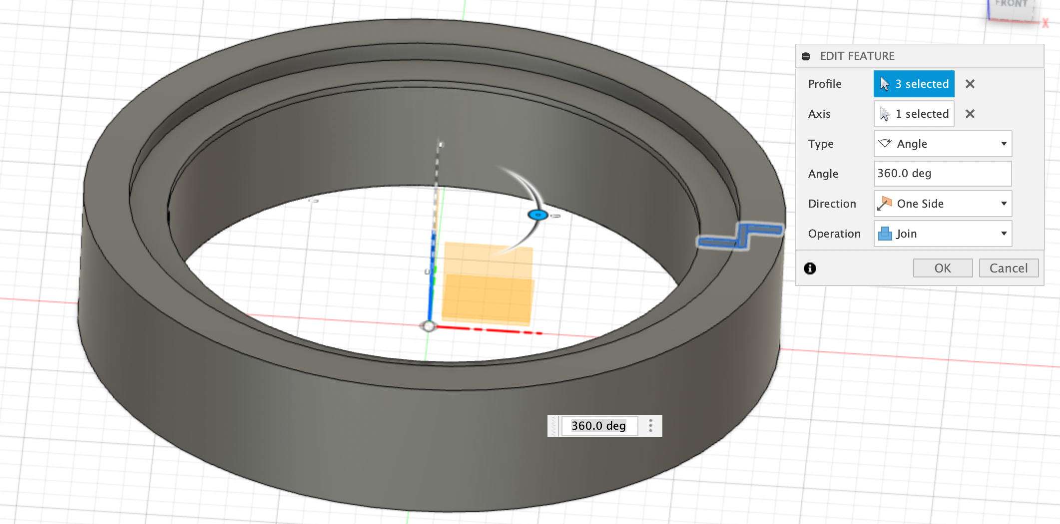
I created another sketch and revolved it around the centre axis so that it would form the brim, and hold up the sift in the middle and joined them.
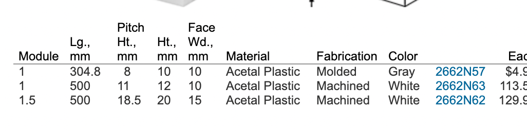
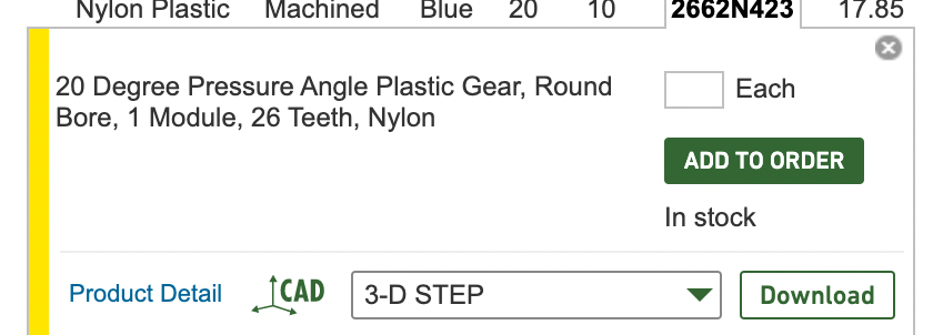
This formed the basic foundation of the body that would hold the sift. I also needed tabs on the bottom of it for it to fit into a base I plan to have laser cut, however I'm going to leave them for later and just use the base to cut them in. Next, I moved on to the mechanism that would move the sift back and forth. Because I'm using servo motors as my machinery, it can only rotate so I need something to change that to a back and forwards motion. To do this I'm going to create a gear and accompanying gear rack. Since those are very finicky to create, (because they need to be even and hand-drawn lines or images taken from the internet don't really do the trick) I took a shortcut and instead inserted a 'McMaster-Carr Component'. I simply searched for a suitable gear and gear rack that suited my needs (something that sounds a lot simpler than it actually is) and inserted it into Fusion360 as a new component. Then I did what adjustments I needed (shortening, ect.) and copied it so I had two. Then I joined the gear rack to the body, which turned out to be a very bad idea I would regret immensely when I spent hours atempting to remove the supports from it.
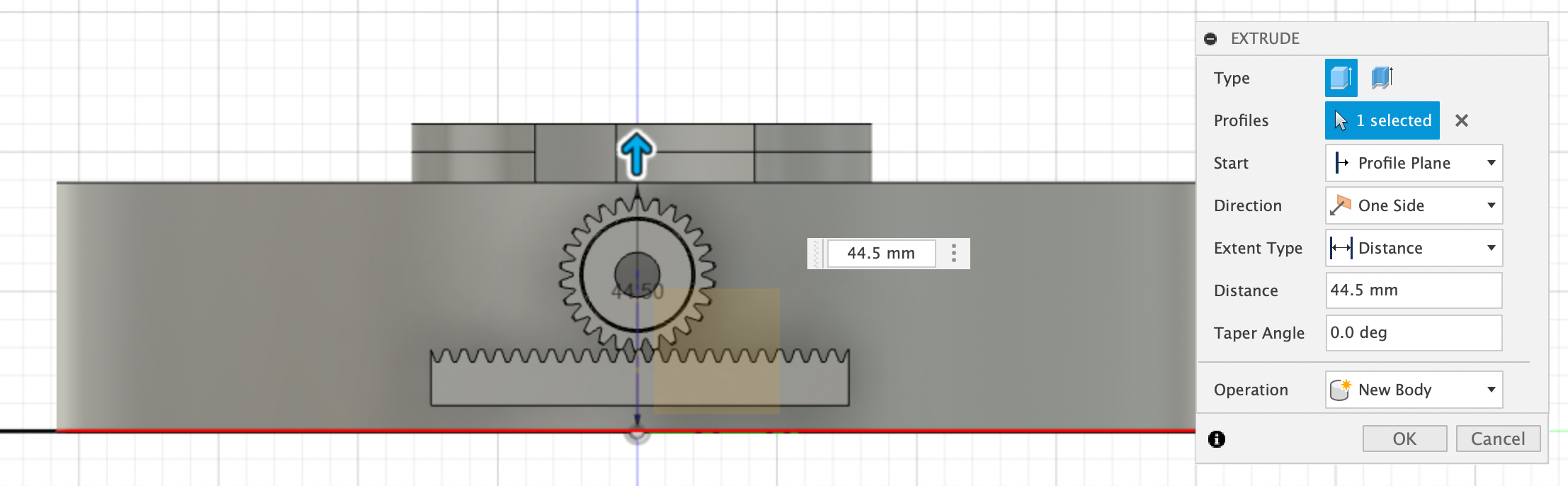
I also had to create a hole where the gear could go through and leave space for the body to move. Halfway along my design, I had a mini existential crisis of HOW THE THING IN THE MIDDLE IS SUPPOSED TO BE FLOATY AND STAY UP, which I eventually resolved by coming up with the idea of supports that the body in the middle could slide along, and be held up by the outer body (this will be explained in the laser cutting process). It was the simplest solution that came to mind at the moment. It would have been more ideal if there was a wheel or track along which it could slide along on, but in lieu of that I... innovated... After creating the supports, I used them to cut holes in the corresponding 3D printed pieces.
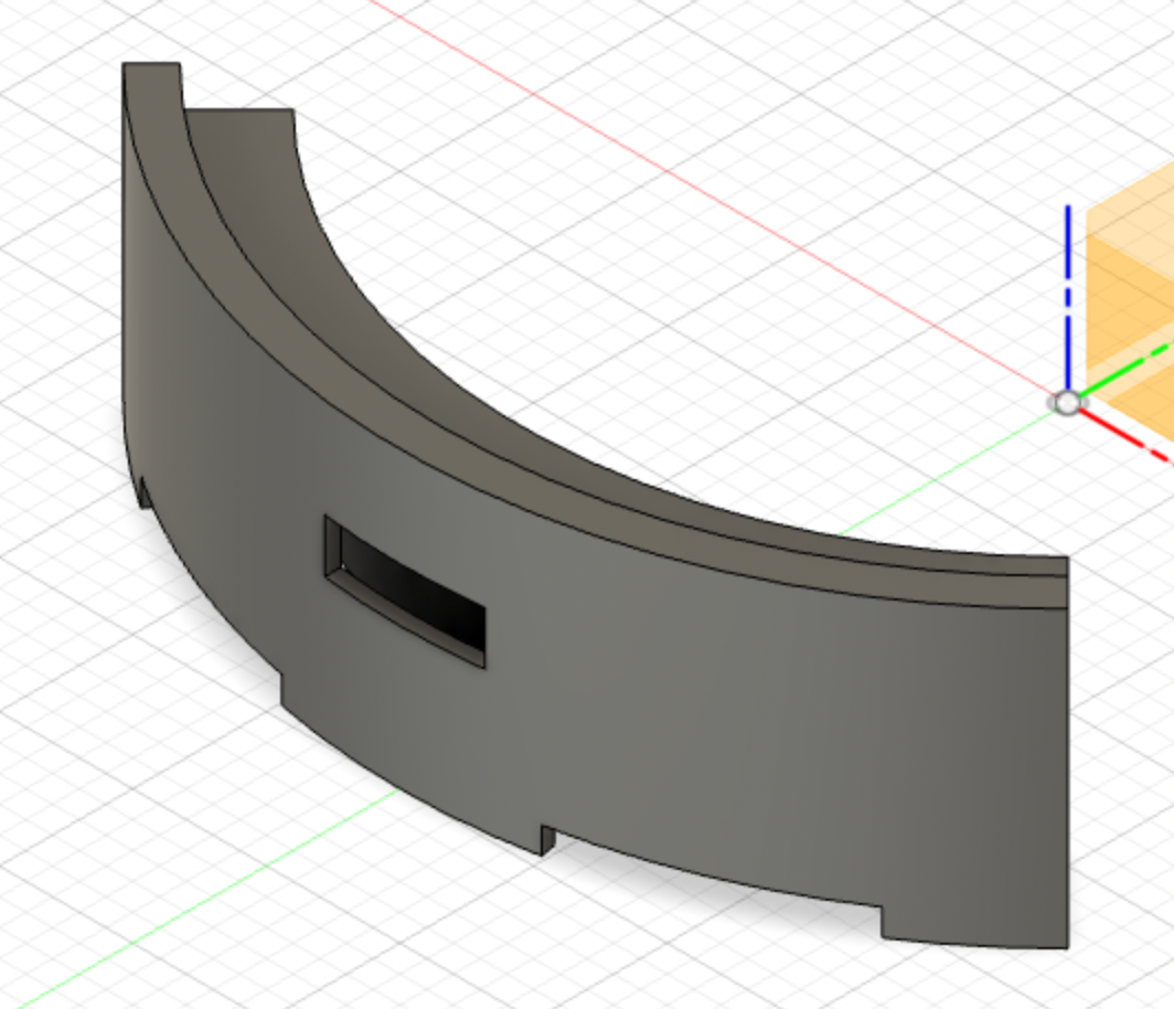
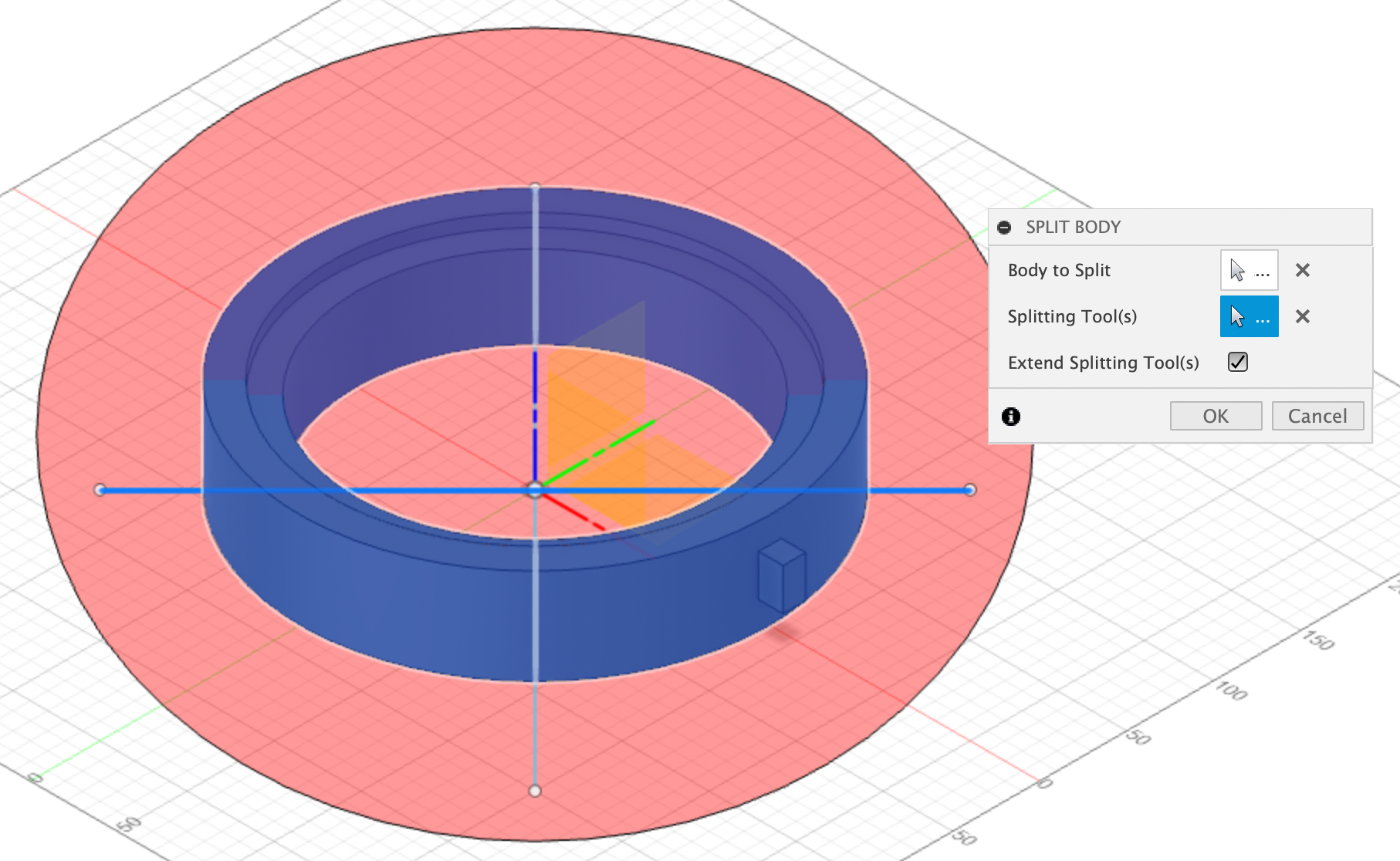
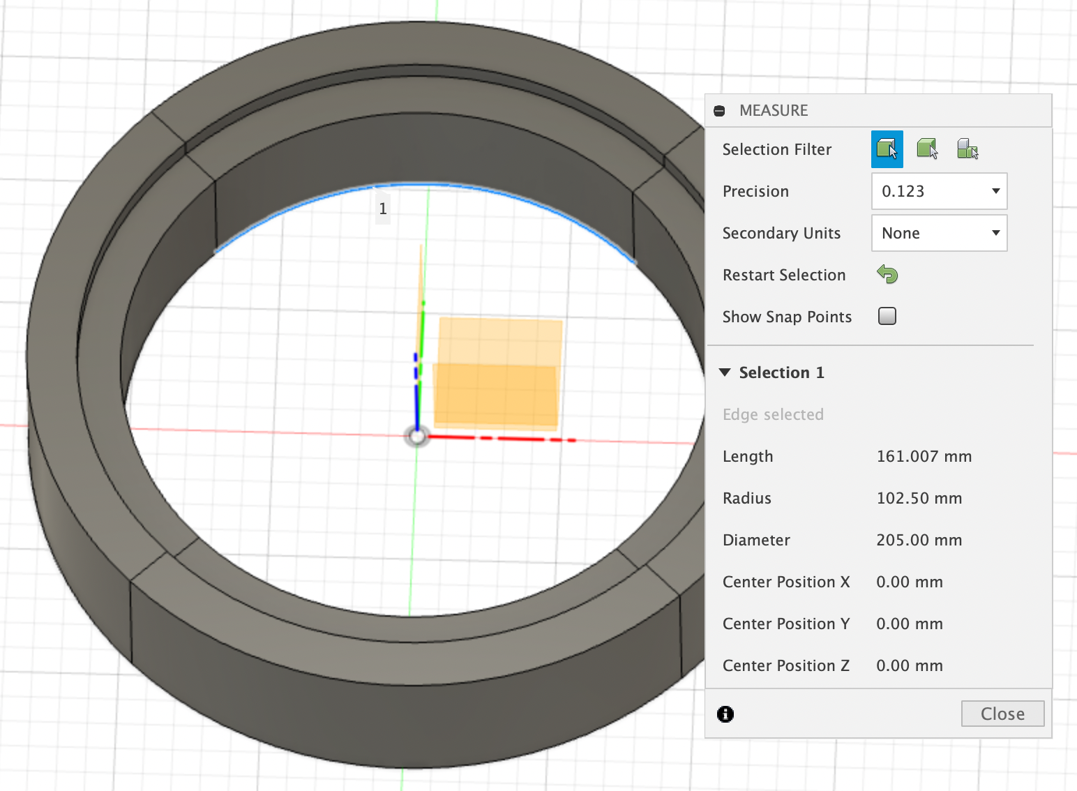
Then, just when I thought everything was essentially completed, I had another existential crisis when I realised that my deisgn was way too big for the printer, which led to me doing math at 1am in the middle of the night trying to figure a way to split it as little as possible and still have it fit. This entire project is basically a record of my incresing anxiety and blood pressure. Splitting it in the 3 was still too big, which meant I wasted a good chunk of my time trying to remember trigonometry, and I eventually caved and decided to split it into 4 instead.
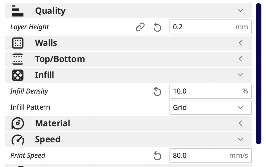
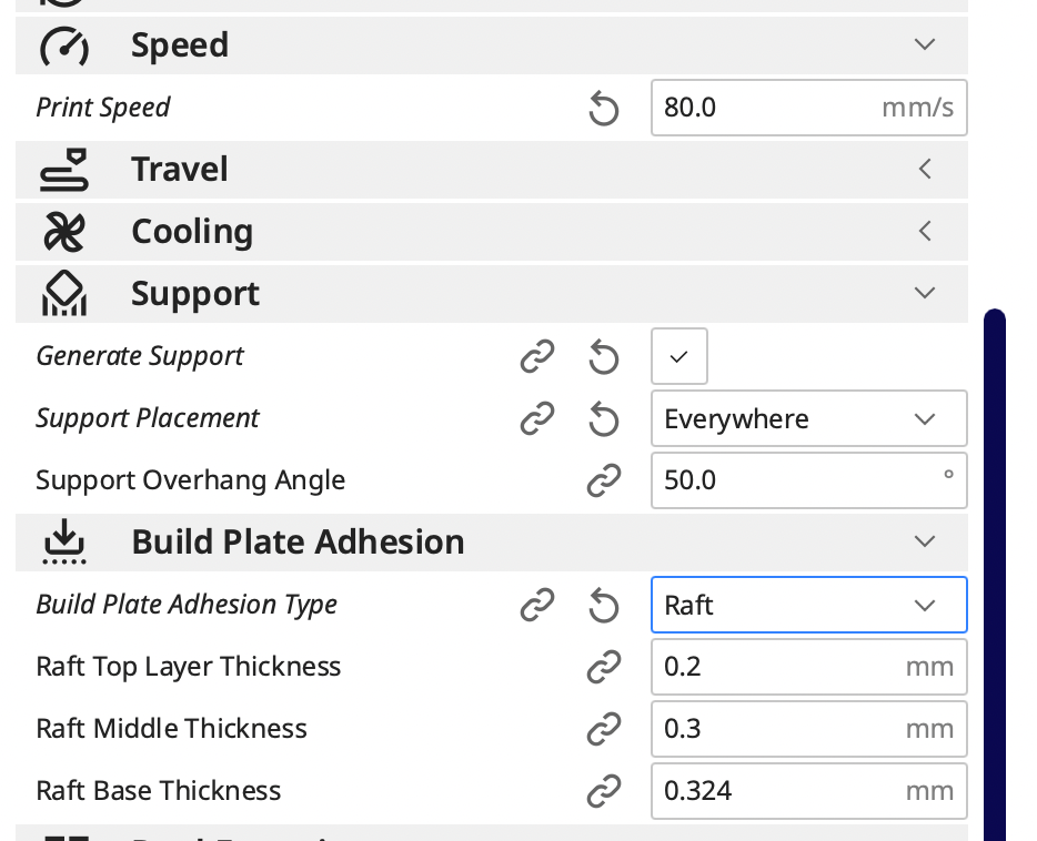
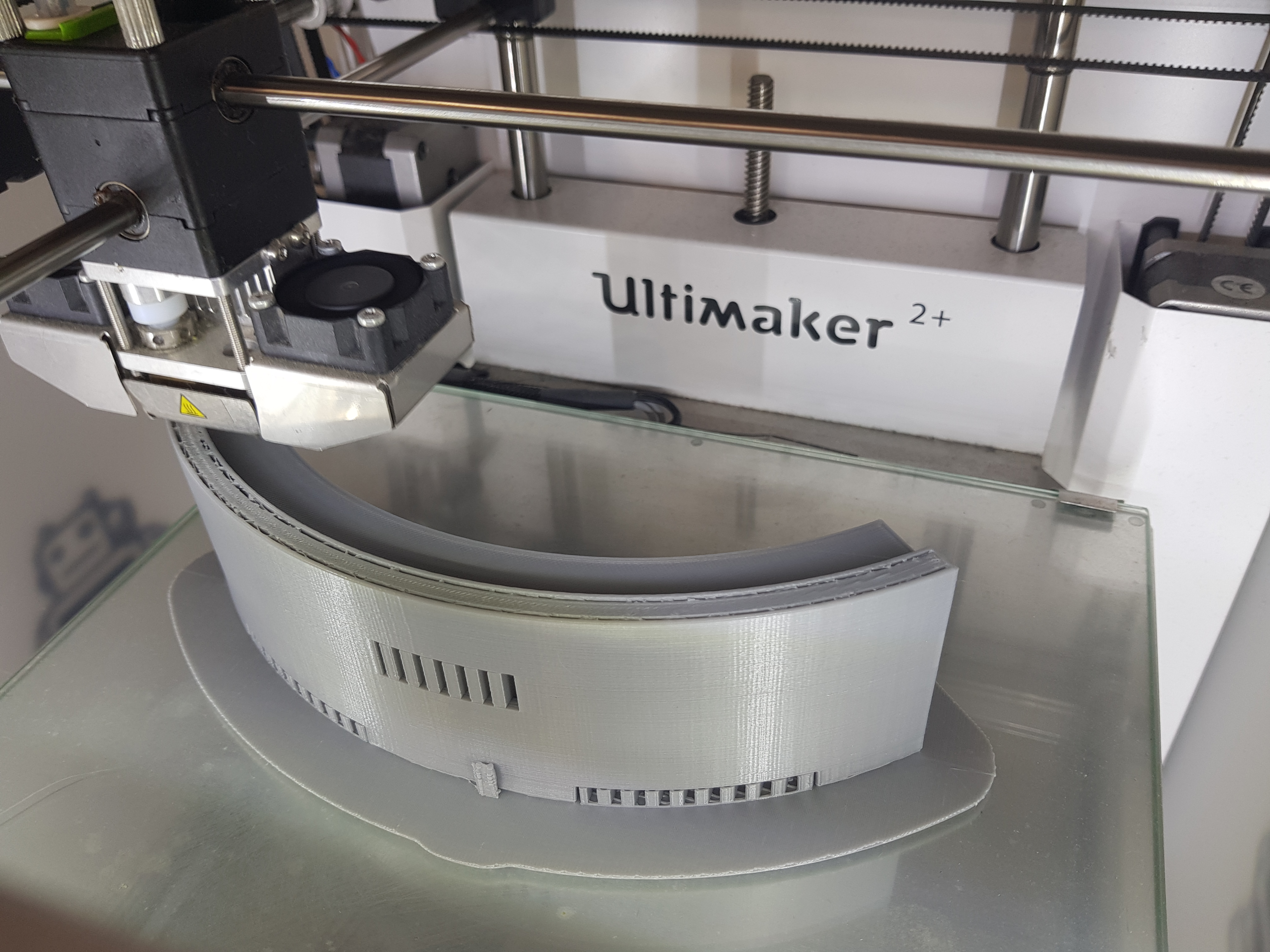
I exported all my 3D prints into Cura to get it printed. Even when it was spilt into 4, each individual piece was still pretty big and took more than 6 hours to print. There were also a few other problems that cropped up, because the 3D printer was down for some reason or other, like the filament not extruding, or jamming. Which meant that I basically had to wait for another day before I could get some of the pieces printed. I didn't want to use a different printer because there was only 2 with the colour I wanted and I didn't want my pieces to be different colours. So essentially it took forever, but I eventually got them all printed.
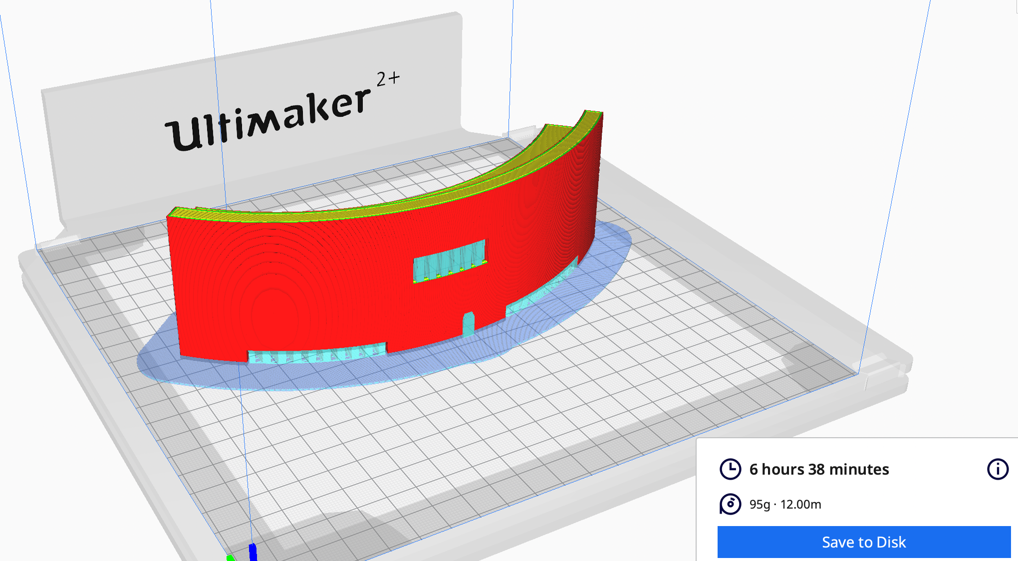
My gears and gear rack took much less time to print—a little over an hour for all of them. I actually decided to split the cylindrical support that attaches to the servo motor and the actual gear itself because I was worried the whole thing wouldn't fit into the corresponding pieces and it turned to be a brilliant decision, because after I got them printed I realised it would be impossible to fit the gear to the gear rack with the support still connected.
But now that my centre body is as done as I have the patience for, it's time to move on to my other nightmare—I mean body.
Laser Cut
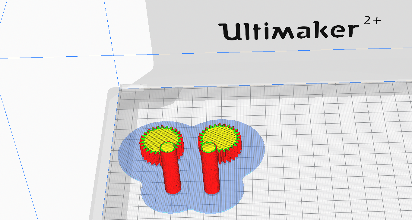
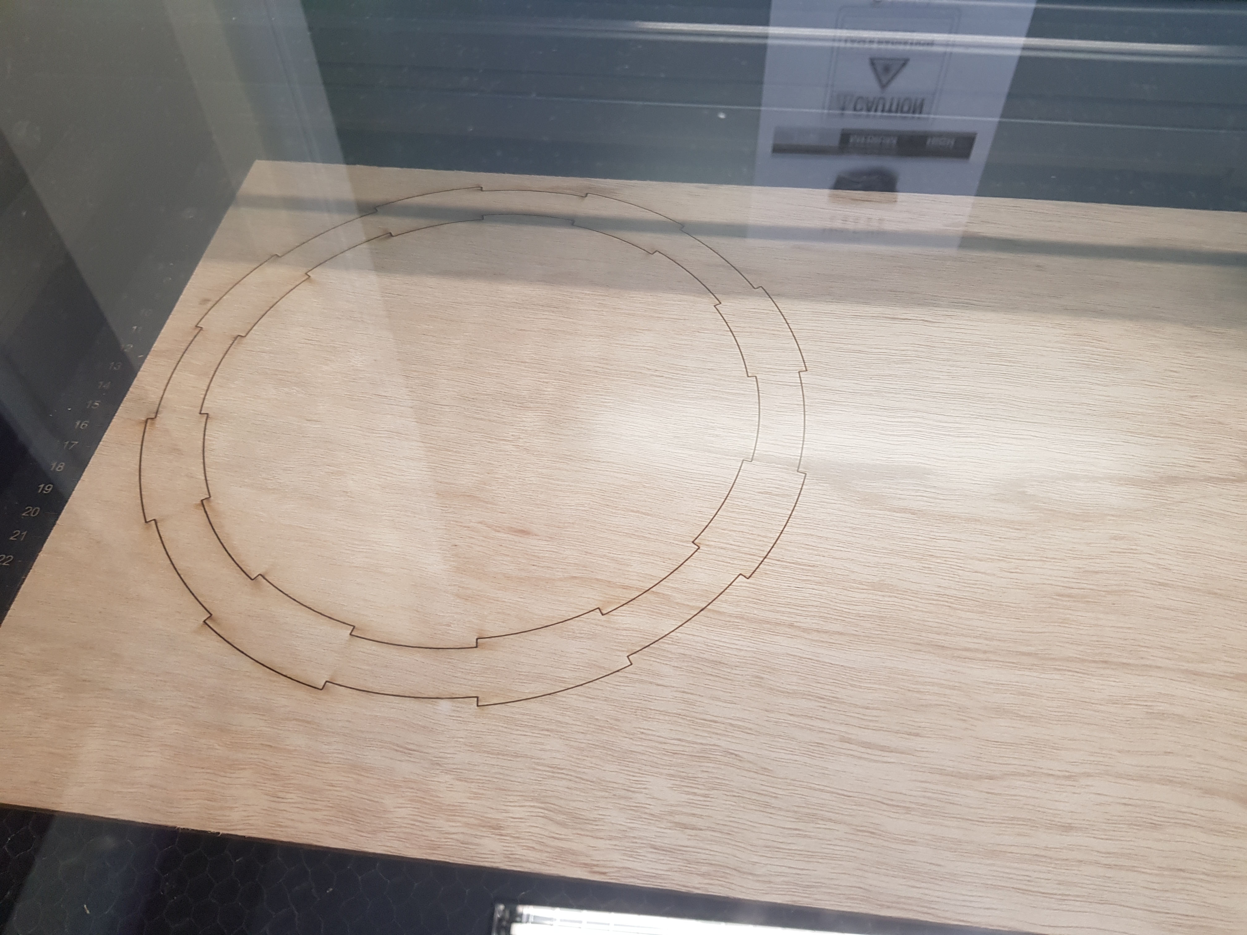
I'm continuing where I left off by creating the base for my 3D printed centre part. I already had the circles from where I made the first sketch, so I just created the base with it. To create the tabs, I drew a line connecting the edges of the walls together, adding a constraint to ensure that it was perpendicular to the edge. Then I created a circular pattern with Fusion 360 and set the angular spacing as full, the centre point as the centre axis and the quantity as 16, which created the sections for the tabs I wanted and also made sure they were all the same size and distance from each other.
Then all I had to do was to select the tabs and spaces I wanted and extruded it by 5mm. I wanted the thickness to be 5mm instead of 3mm because I wanted the 3D printed pieces to have a little more grip so they'd be more sturdy and easier to assemble. I then used the base to cut the tabs into the 3D printed centre pieces. In this way, the base is one whole piece that would hold the 4 seperate centre pieces together.
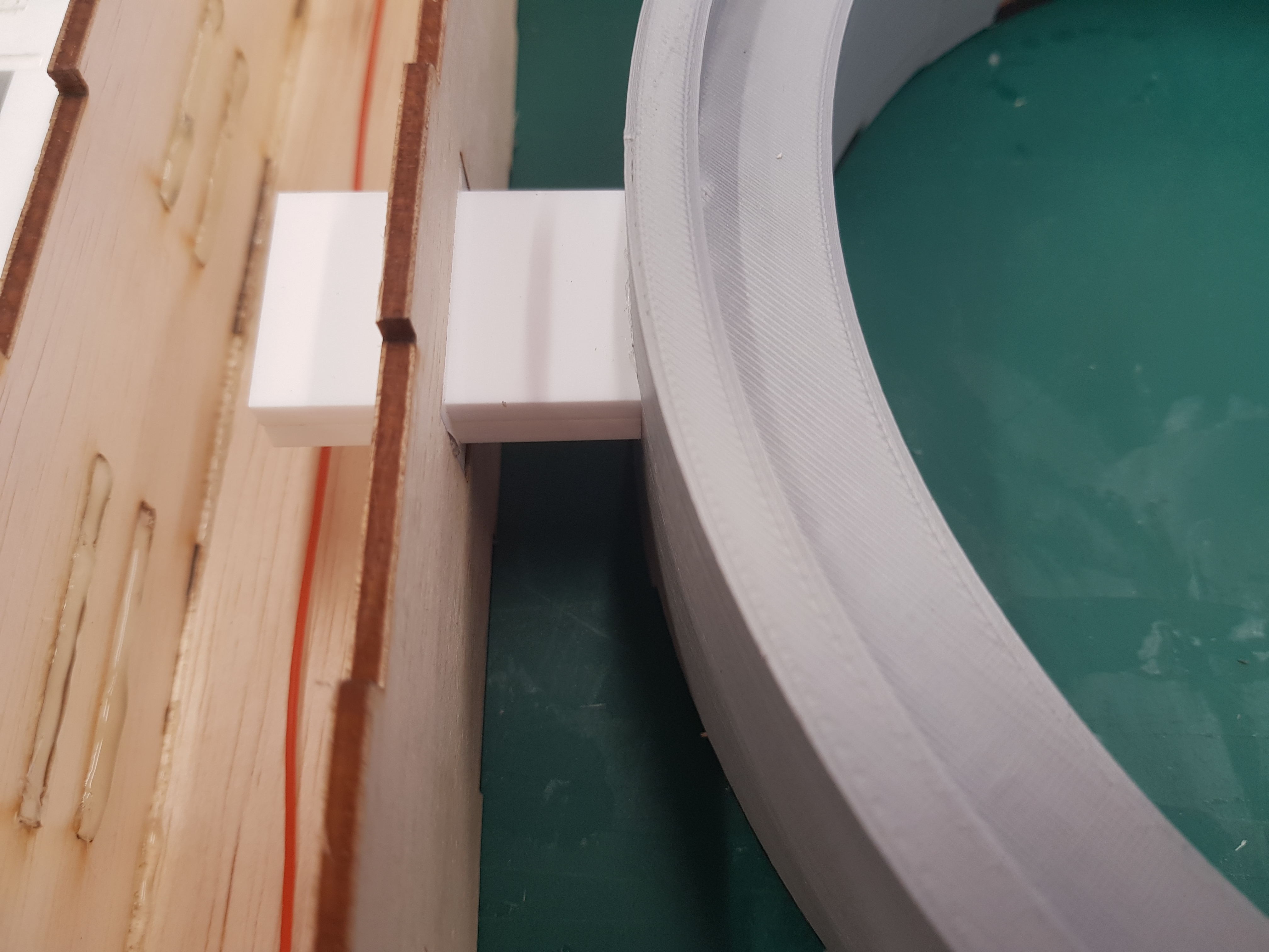
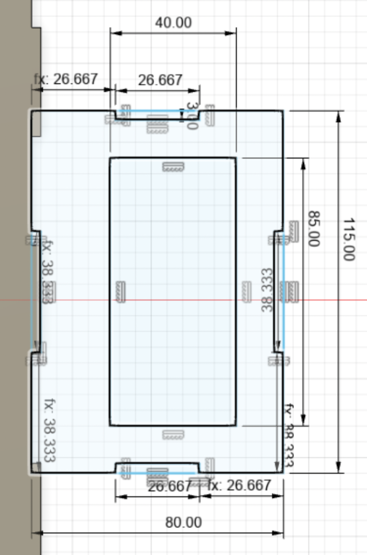
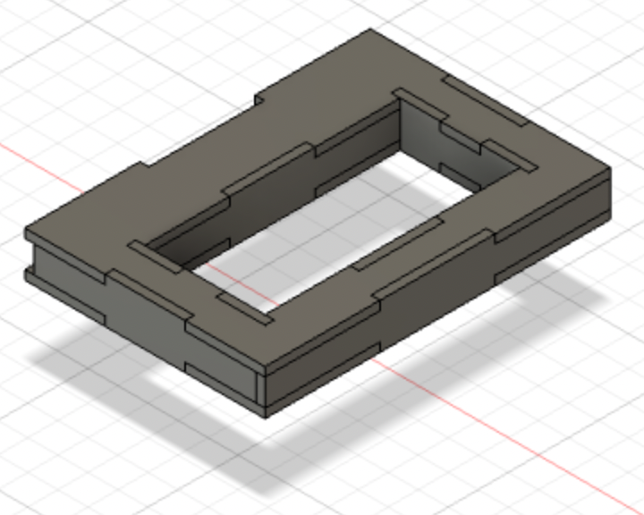
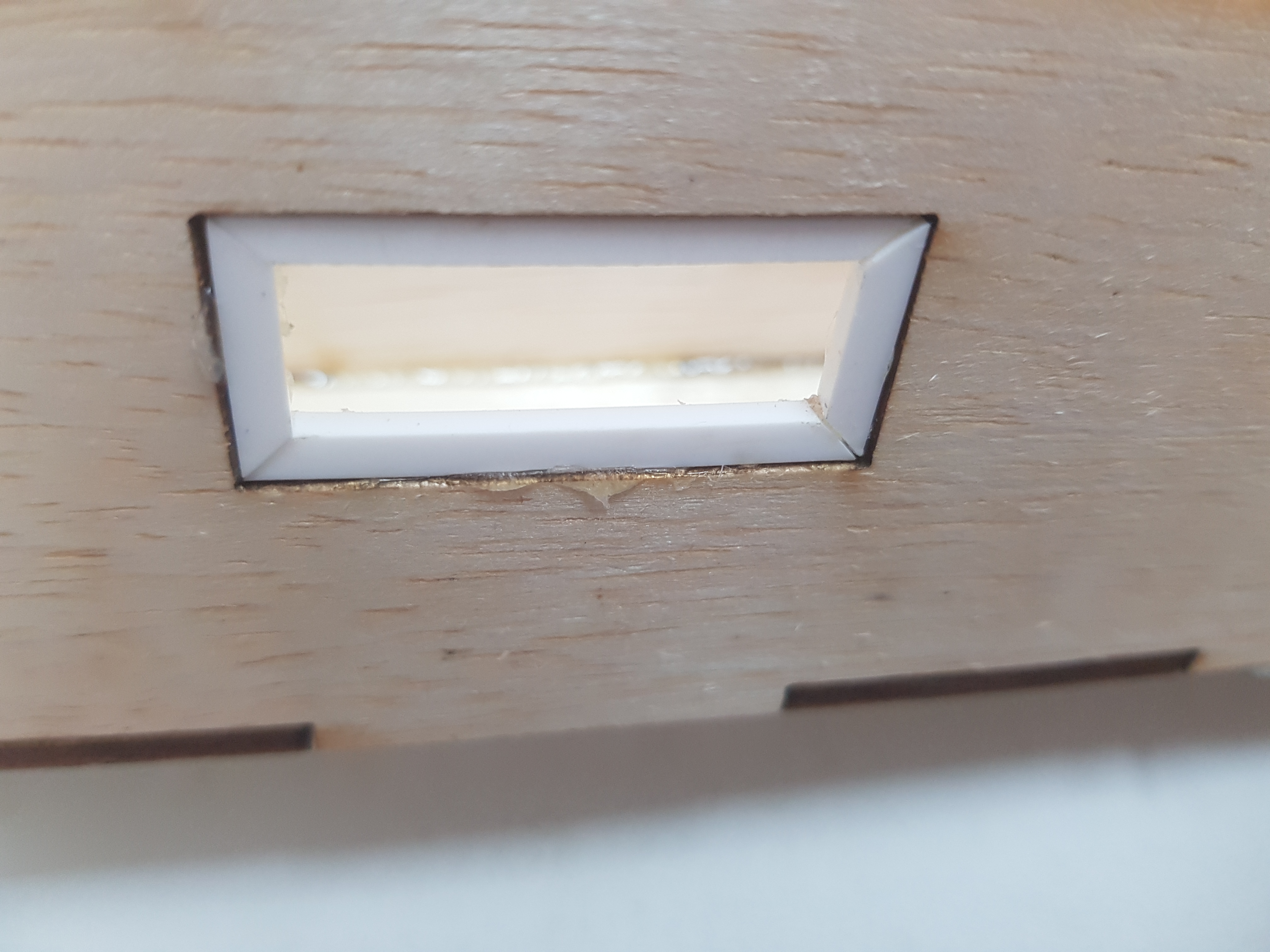
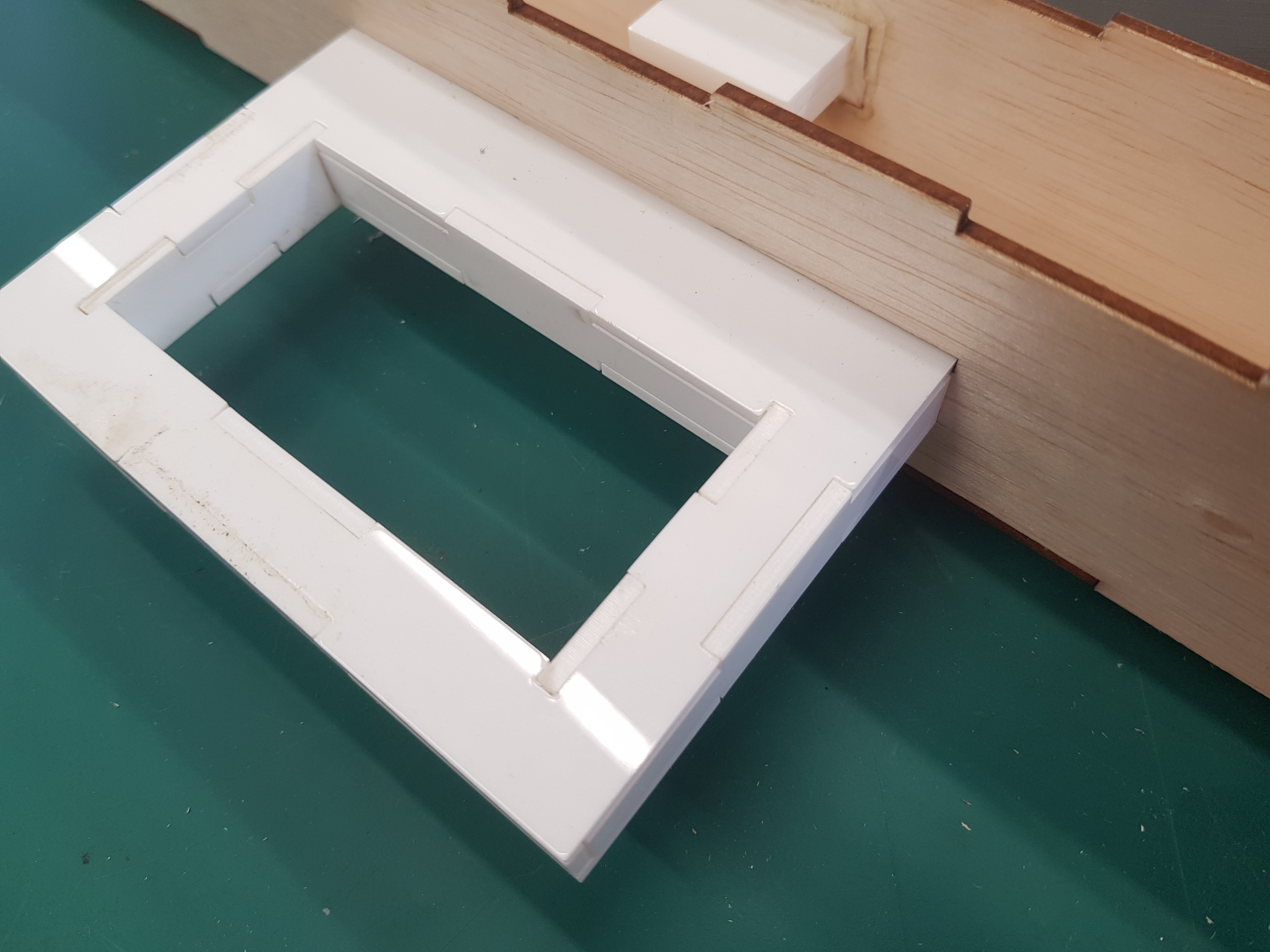
Then I dealt with the problem of supports. It was basically just a rectangular block measuring 45x30x10 that attached to the corresponding 3D printed part. I used the 3D part to cut out the shape of the supports so it would fit the curve of the walls, then moved them to where I wanted them to be. Then I used the supports to cut holes in the 3D printed part so they would fit perfectly. I also thought of the idea of making 'frames' where the supports could slide on, so I created a couple sketches for them.
I actually designed it so one frame was made out of four pieces which I could then glue to the edge of the hole in the wall of the outer body, but in retrospect, I'm wondering why on earth I decided to make one frame out of four pieces when I could have just created a whole rectangular piece with a hole for the support. It could have saved me time, effort, and hot glue gun burns from attempting to glue it in place. Anyway, I used the frame to cut out a hole in the wall of the outer body which completed my design for supports. I cut the support itself out of 5mm thick acrylic, and I then glued 2 pieces together with glue made for acrylics. The frame was also made of acrylic, and this was to reduce the friction of sliding along each other as much as possible.
This pretty much completed my centre piece, so I could now move on to the outer body that would contain all the machinery for the embedded programming and hold the centre piece up.
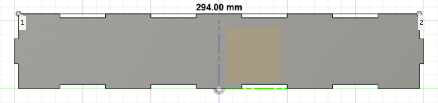
I started by creating parameters that would make things easier for me to modify if I needed to later in the process. I set the length as 300mm, the height as 55mm, and the thickness as 3mm. I also set the number of tabs on the side and along the length. Then I just created a new sketch according to the parameters and included all the tabs in the sketch. I extruded it by the thickness, which gave me the first wall of my outer body.
I followed the same process for the adjacent wall, but left out the side tabs in the sketch because I could just use the first wall to cut them in perfectly. Then after I cut holes for the supports, I copied and moved the two walls to where I wanted them to be and did all the subsequent cutting so the tabs fit into each other.
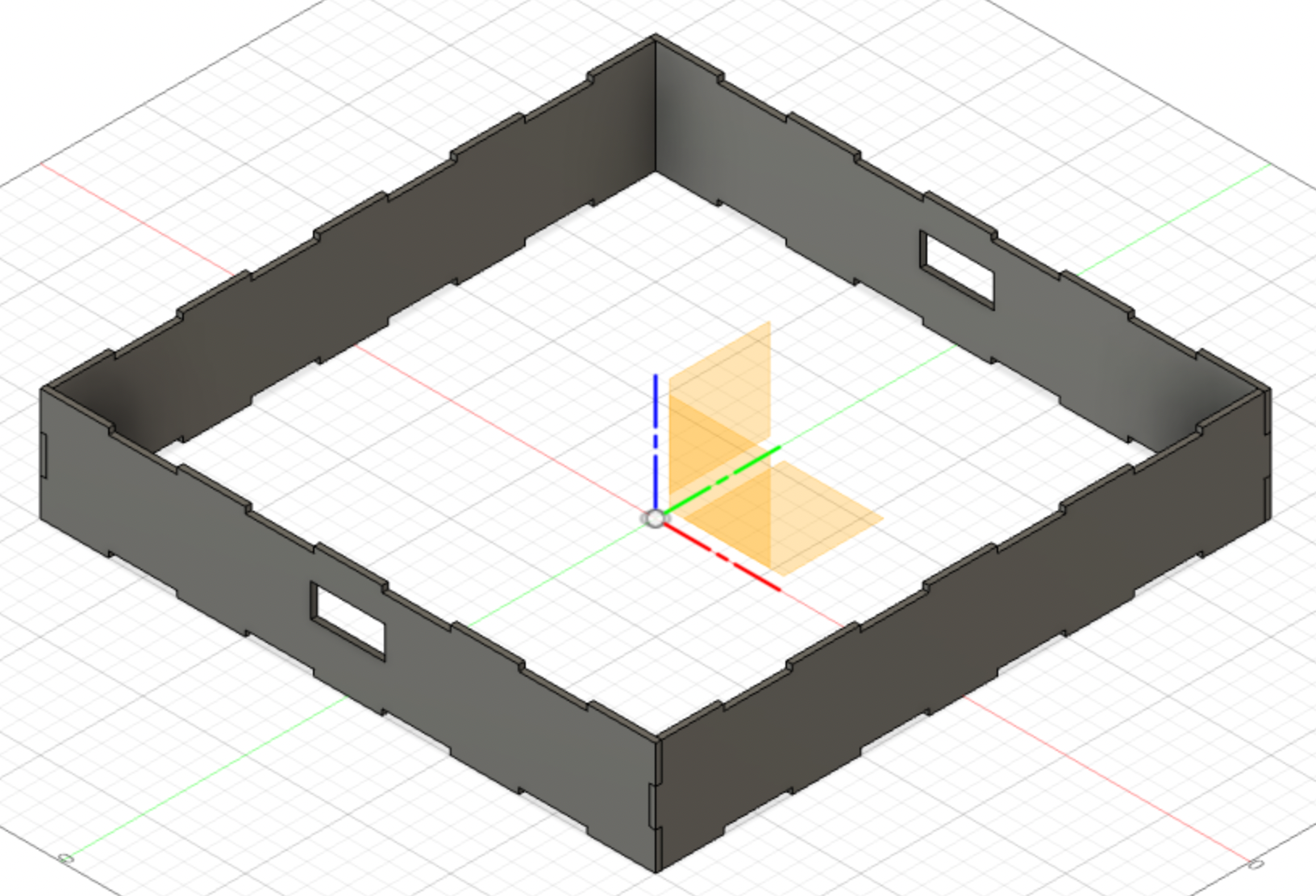
This completed all the inner walls of the outer body. You may have noticed that I didn't include holes for the gears to connect to the servo motor. The reason behind this is that I was afraid the gear wouldn't be perfectly aligned with the gear rack, which was very important or the centre piece wouldn't be able to move. So I decided to just drill the holes in myself after I've cut all my pieces and see eaxcty where I should have the hole.
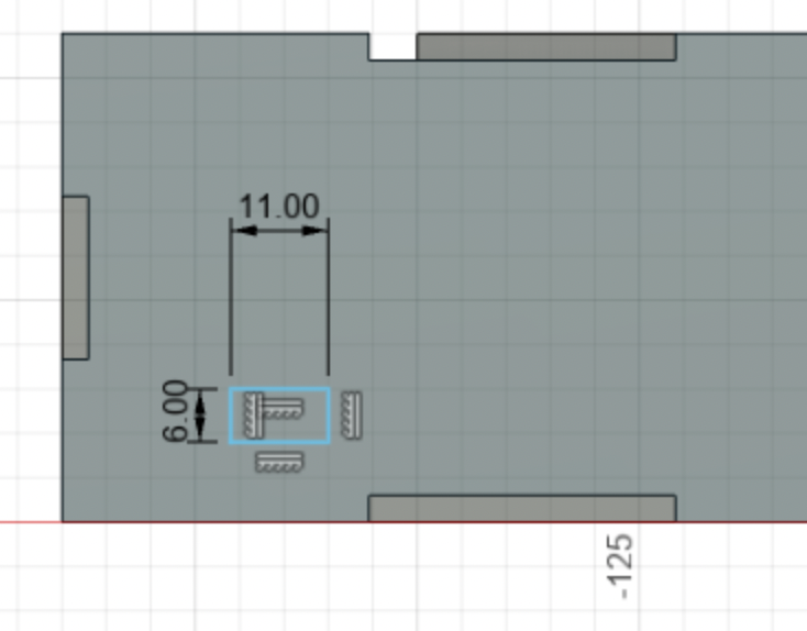
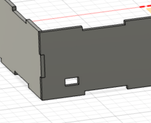
For the outer walls I followed the exact same process and added a new parameter for the length, which was 380mm. This gave me 37mm of space between the inner walls and the outer walls, which was enough to contain all the machinery, including the servo motors and gear attcahments. It also gave the needed space for the supports to slide around. Then I just created the adjacent walls and copied and moved them to where they were supposed to be. I also didn't forget to include a hole for the switch.
Then I created the base and top of the outer body. I created a sketch and extruded the part I needed, then used the walls of the outer body to cut the tabs into it.
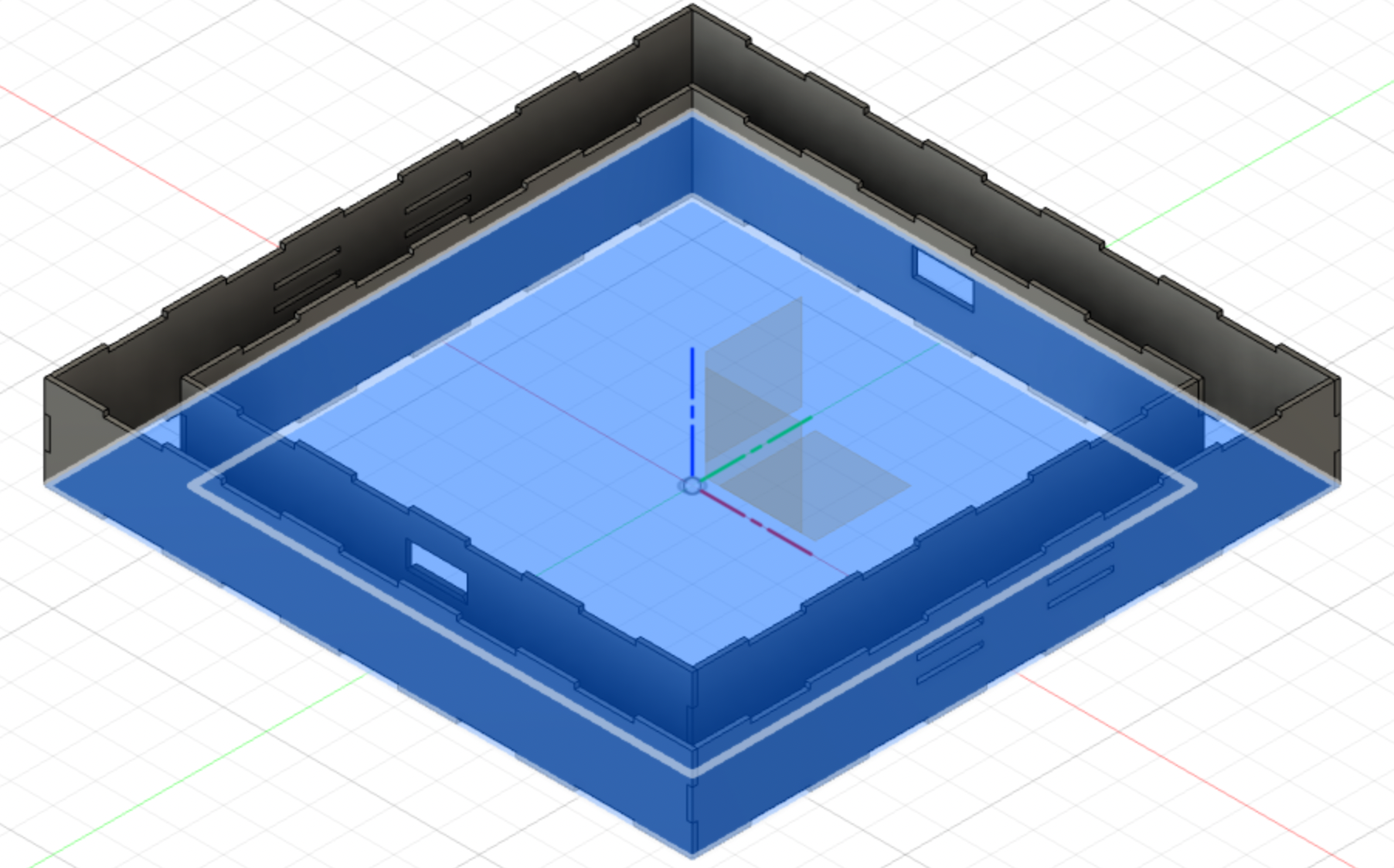
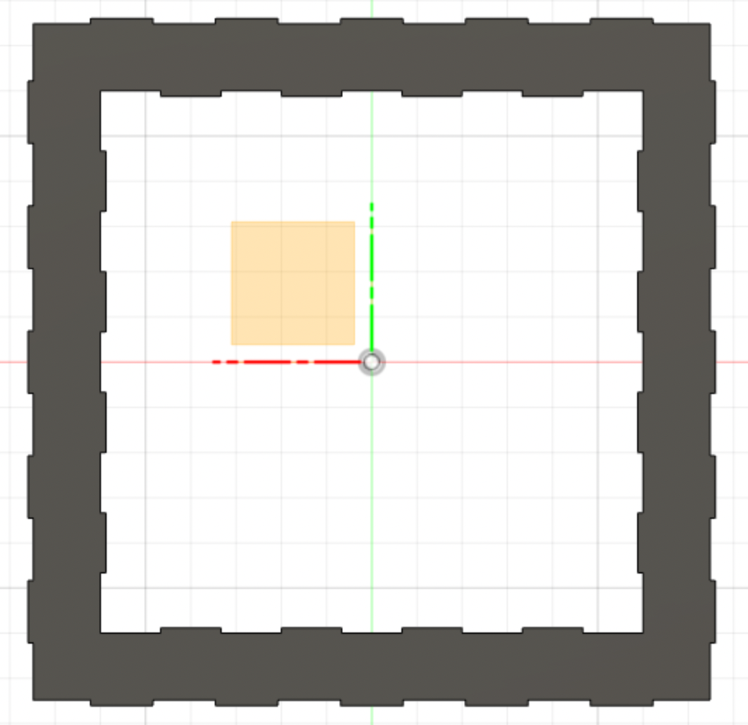
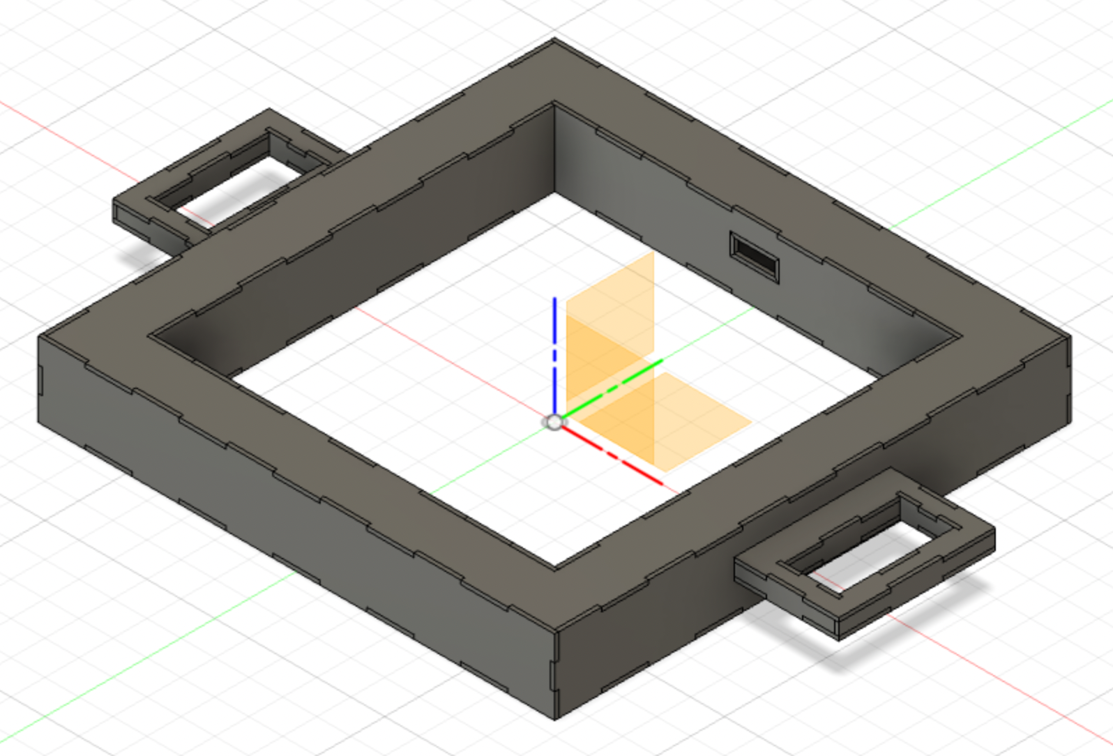
I then copied and moved it for the top, which basically completed my outer body. Except... it was time to create the handles. I wanted the grip itself to be 15mm thick on all sides. As always, I started with a sketch, extruded it, and moved it to where I wanted it to be. Then I coopied and moved it for the top, and started designing the other walls of the handles. I moved and copied the whole handle for the other side, and used the handles to cut holes in the corresponding walls for them to fit into.
The entire handle is going to be cut out of white acrylic for aesthetic purposes, and also because it's the part you hold and it makes snese for it to be sturdier and waterproof. And here is the finished outer body!
2D Design
I also wanted a laser engraved design on my outer body, so I searched online for a few nice baking-related designs and found two that I really loved. I actually intended to put one design on the top cover of the outer body, and the other on all four outer walls of the outer body. However, I eventually decided against engraving on all four walls which I'm glad for now, because it would have been way too much, not to mention taking forever. So I went on Adobe Illustrator, imported the design I found into it, and did an image trace of the design. Then I used the dxf of the top cover and used it as a clipping mask, giving me the shape that I wanted. I also added my initials to the corner of the deisgn, then used the 'type on path' tool to write 'Deliciousness Awaits' on a curve that I also created using the pen tool. I did a few more minor edits to make sure the design didn't cover the text, and I was done.


Embedded Programming
Okay! Programming. My source of endless frustration. I had a lot of roadblocks with this because I have no experience whatsoever when it comes to embedded programming so I was very out of my depth. Heck, I didn't even take physics.
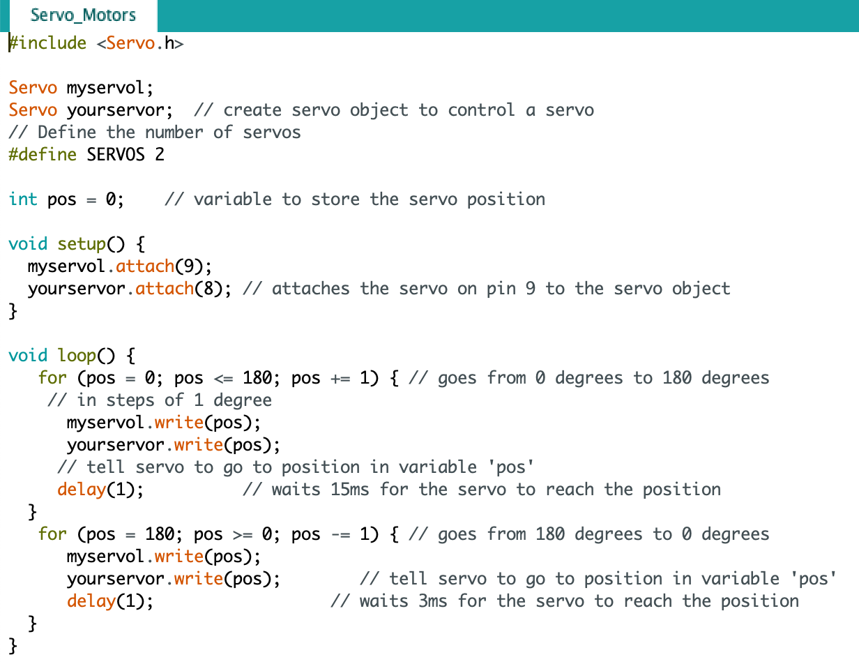
It wasn't the code that was the problem—although I had a few issues with that too—it was mainly the wiring. But let's talk about the code first. I essentially went on the internet, and searched for codes for servo motors and copy-pasted it into arduino.
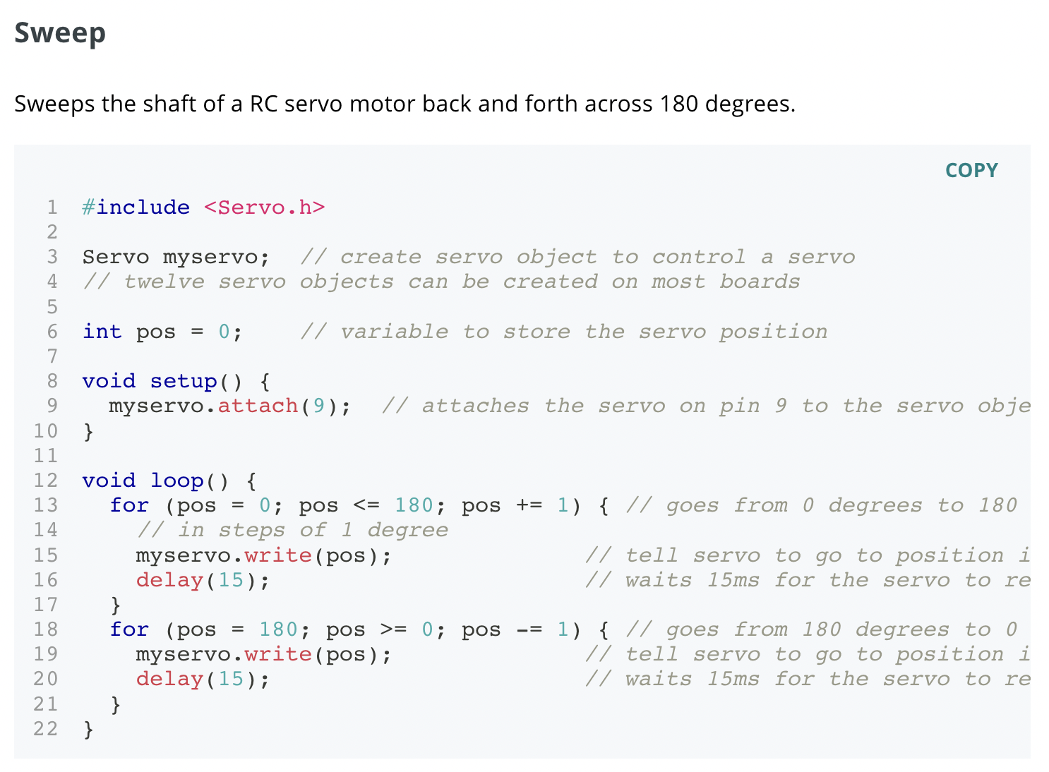
I used this basic code as my foundation, and through the help of Google, figured how to turn it into one controlling more than 1 servo. I changed the delay time to 1ms, and then I was done with the code!
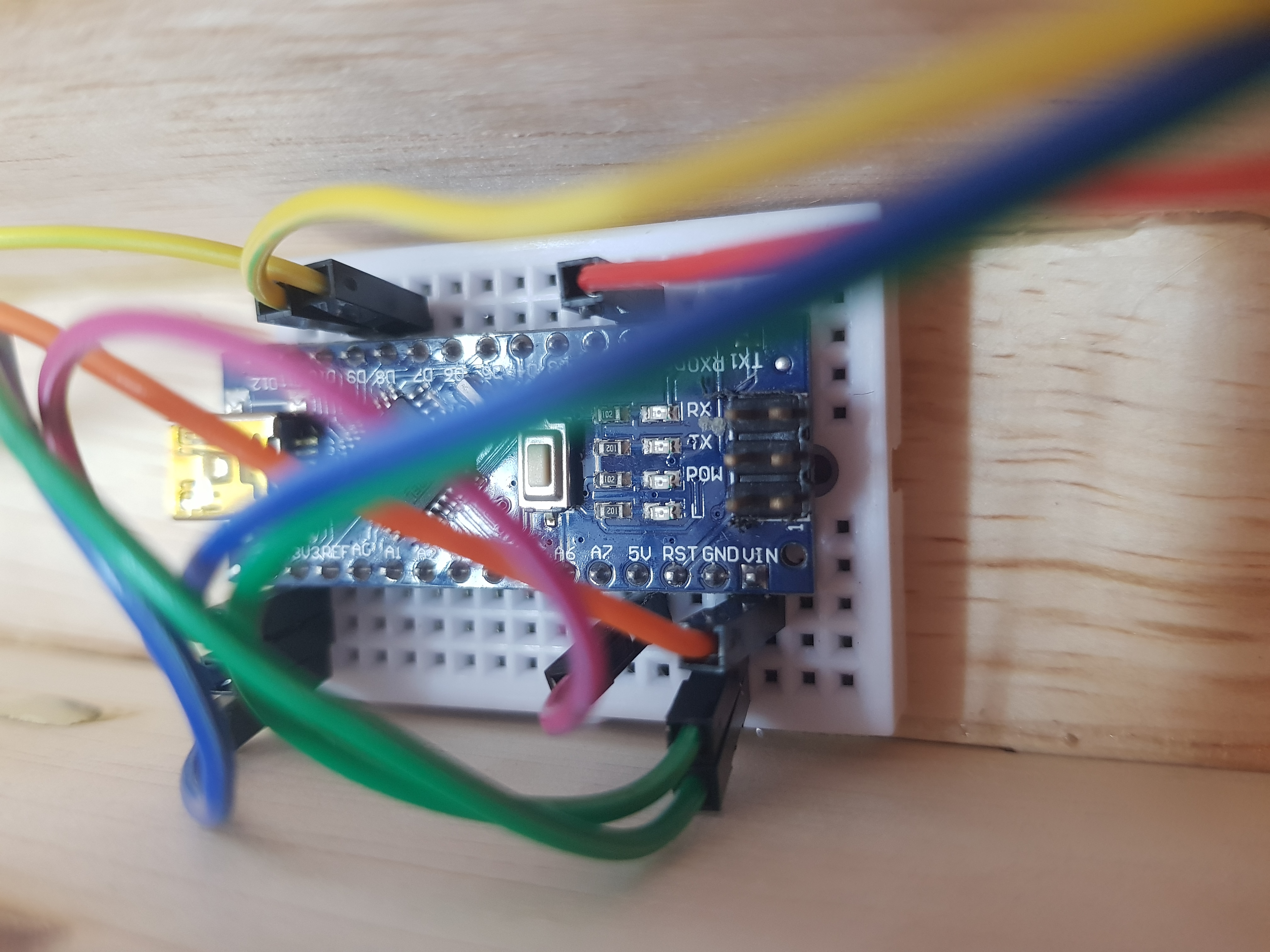
However, even though my code was working, my servo motors didn't respond well. I initially planned to use an arduino nano because of it's smaller size, but for some reason it just wouldn't work no matter what I did. I'm pretty sure I just wired it wrong somehow, but at the time, I was so annoyed and confused that I just gave up and switched to an arduino uno to see if that would work better. And it did! It just didn't work perfectly. With the arduino nano, there was no response at all. With the arduino uno, only one servo motor responded. So I was basically at a lost, until I asked for help from my lecturer and realised that my wiring and code were all correct— except the wires connecting to the servoo motor.
A servo motor has 3 wires, all of a different colour and I basically plugged my wires in the wrong way, so they weren't connected to the correct wires. So after that was fixed, both servos worked perfectly. But then I realised my arduino uno was just a little too large to fit into my outer body, because that was designed with the assumption that I would use the arduino nano. So my lecturer told me to switch to one, and it worked this time round, which I guess means my wiring was wrong when I first tried it with the nano. I also wired it to a slide switch, and was planning to use a 4.5V three-battery pack, but the current was too low and the servos couldn't work properly. So another lecturer suggested for me to use a 9V battery, but warned that even that might be too low. And he was right! The servos worked, but the movement was jerky and not really in sync unlike when I power the ardunino nano with an external power source.
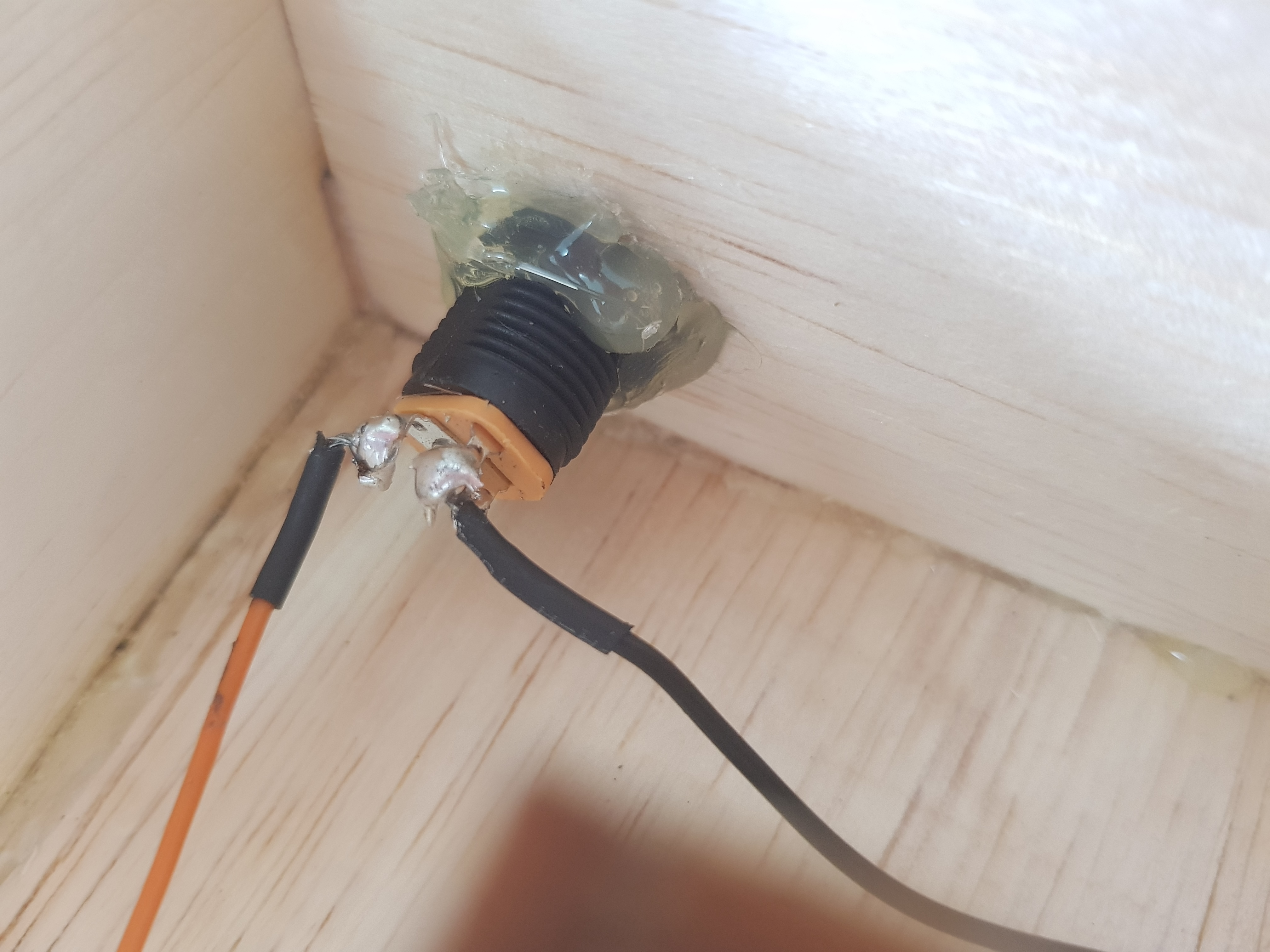
In the end, I just decided to use an external power source and rewired my wires to a barrel jack.
Assembly
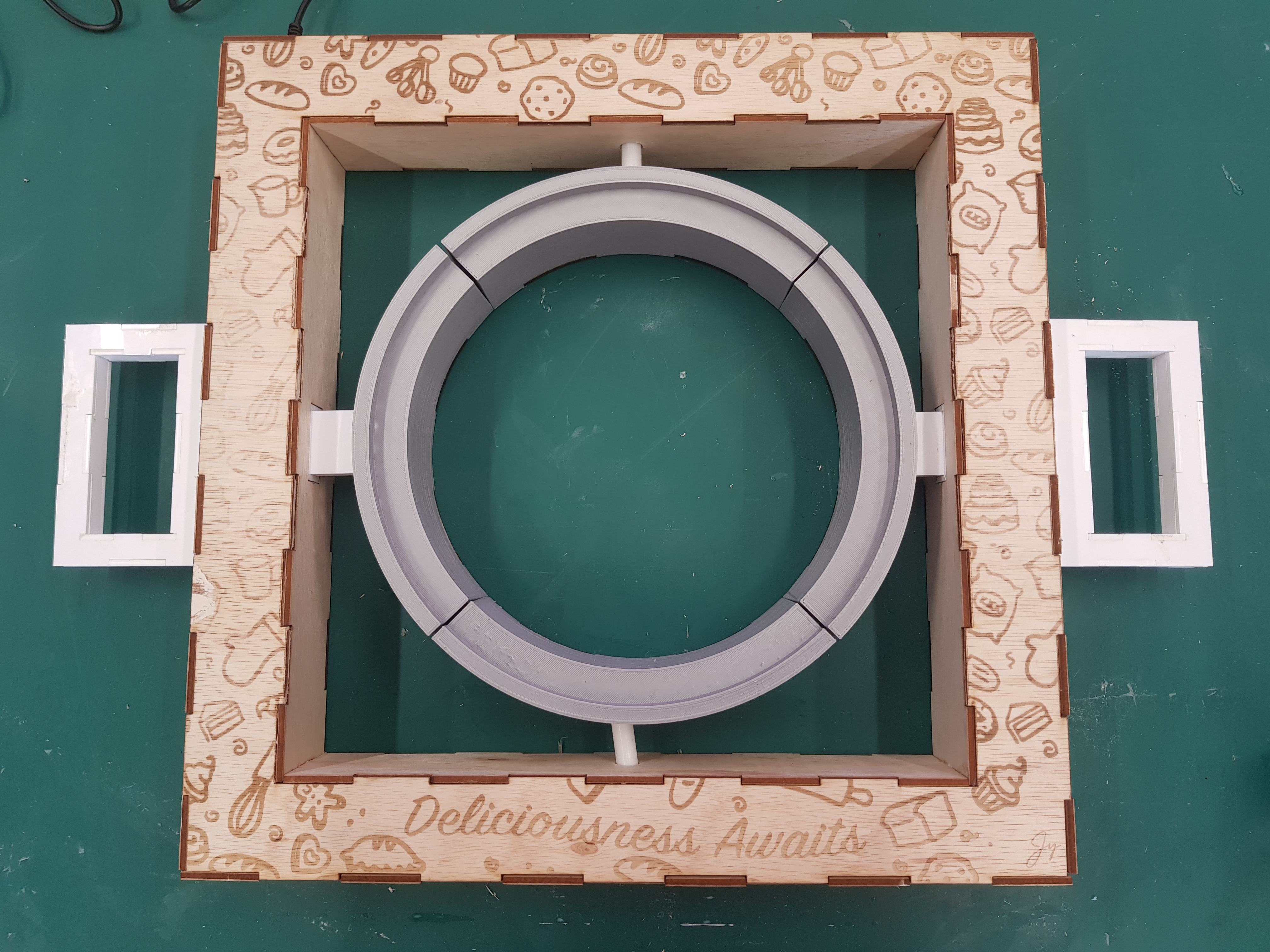
Time to assemble everything!
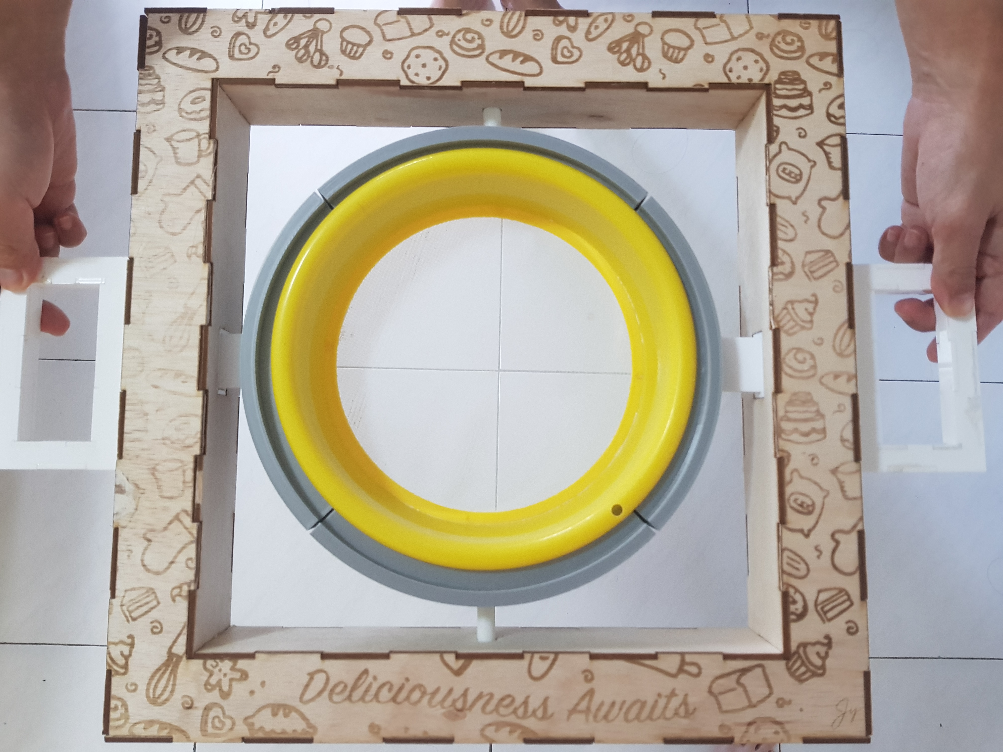
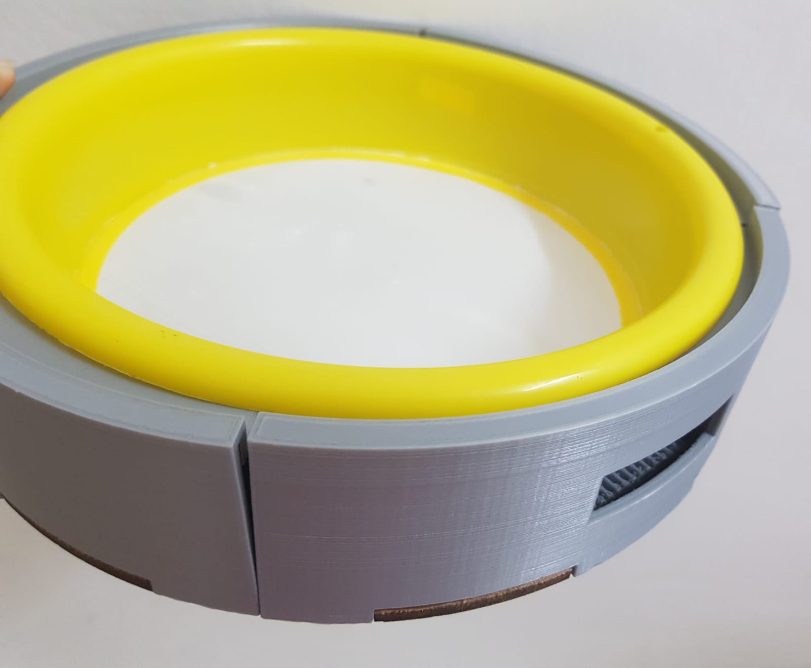
I got all my 3D printed stuff printed out, and fit the centre piece into the base. Much to my relief, they fit into the lasercut base perfectly and my sift fit perfectly into it too. However you can see that there's a sort of crack where the pieces next to each other don't line up to each other perfectly because they were made with no extra space in mind. It's not a huge problem, but I think I would leave maybe a millimetre of space on the sides if I reprinted it, just so they would line up to each other better.
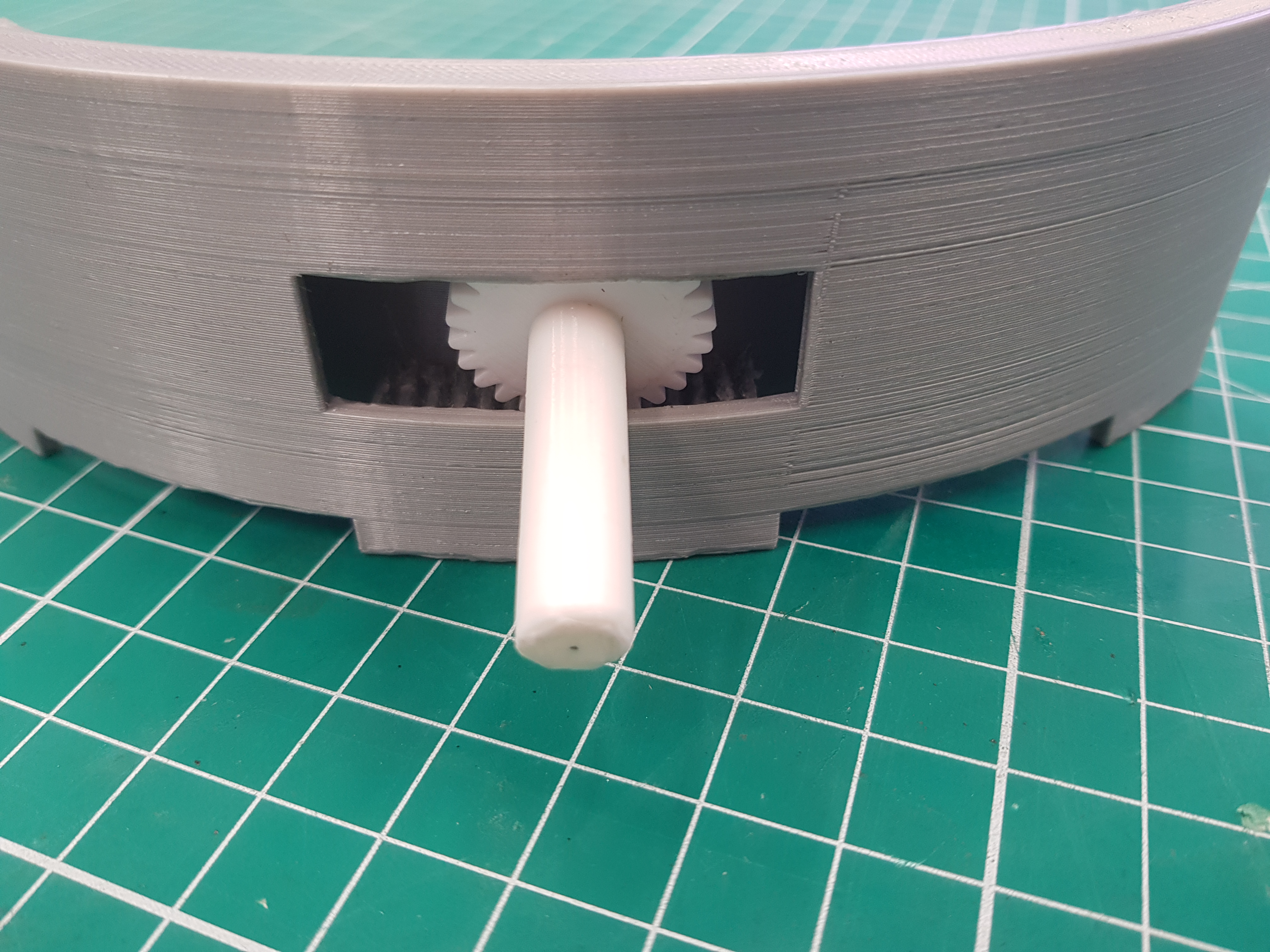
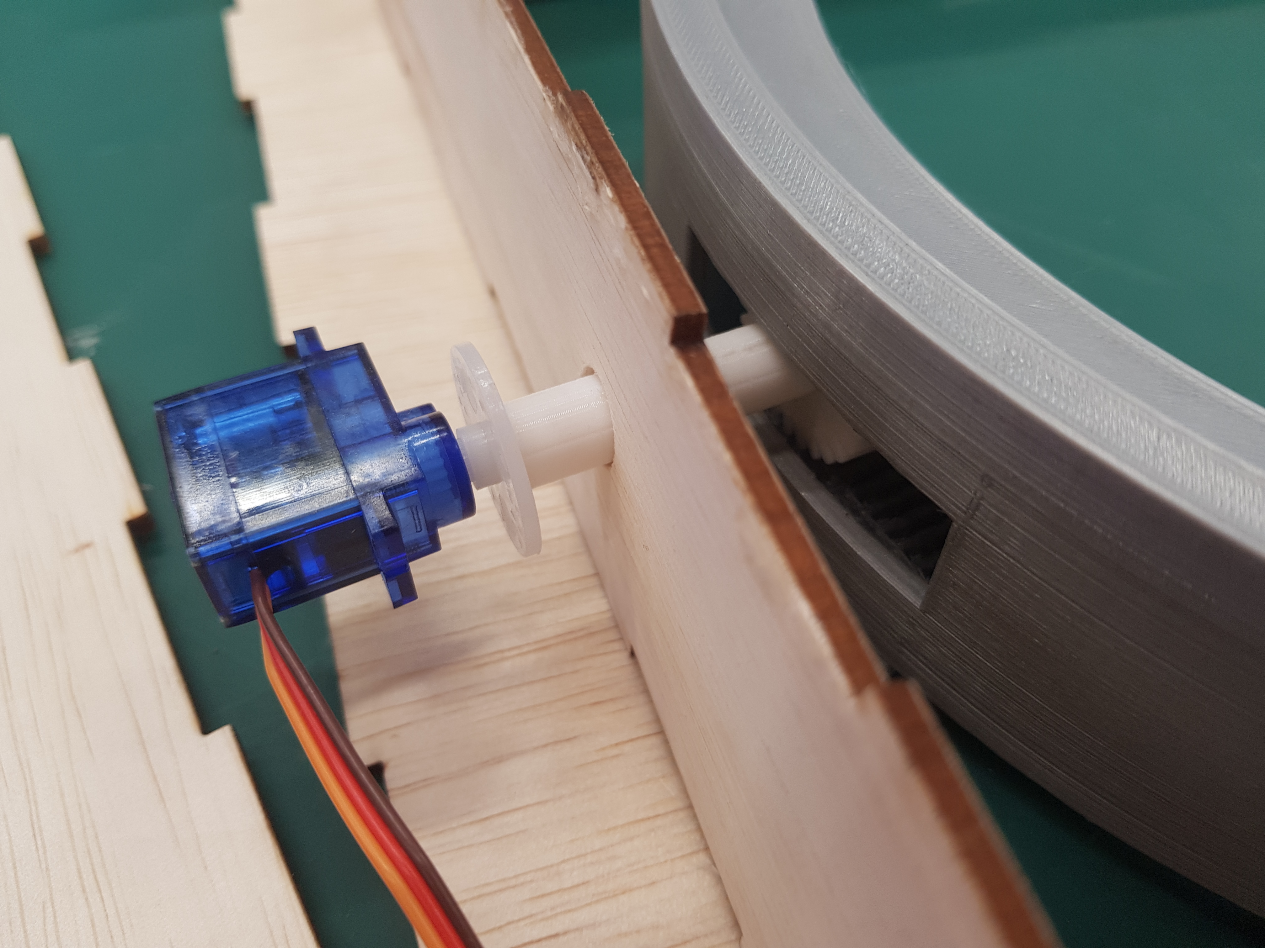
For the gears and connecting gear support thing, I sanded them down as smooth as possible and attached them to each other with some glue through the wall of the piece. It makes more sense visually. Then after I manually drilled a hole into the corresponding walls, I connected them through the wall and to the servo motor attachment.
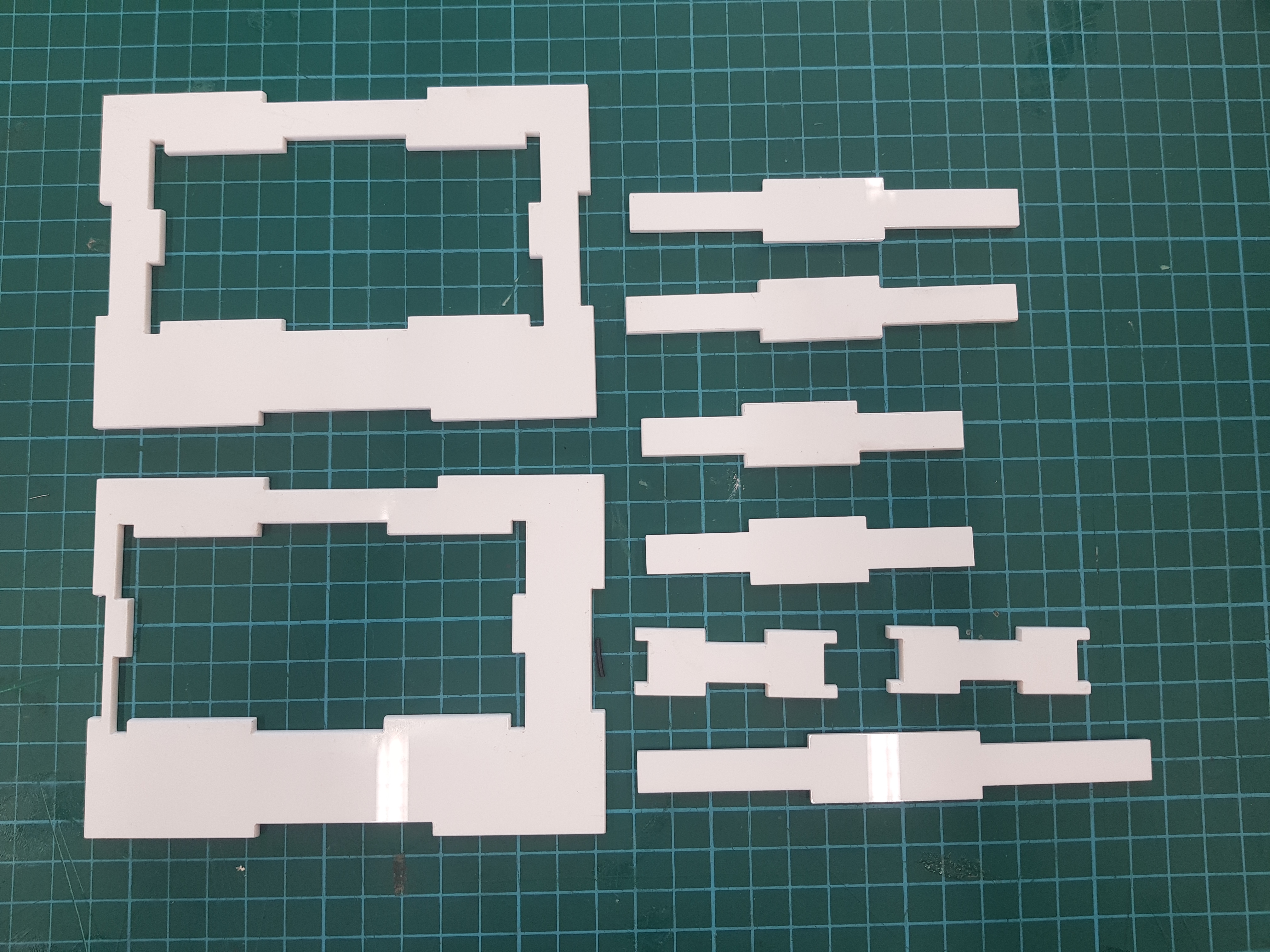
I also lasercut all the laser cut pieces out of their respective material/thickness, and glued them together. Also, this is what I mean by my extreme stupidity in making the support frame out of four pieces instead of just one.
Handle:
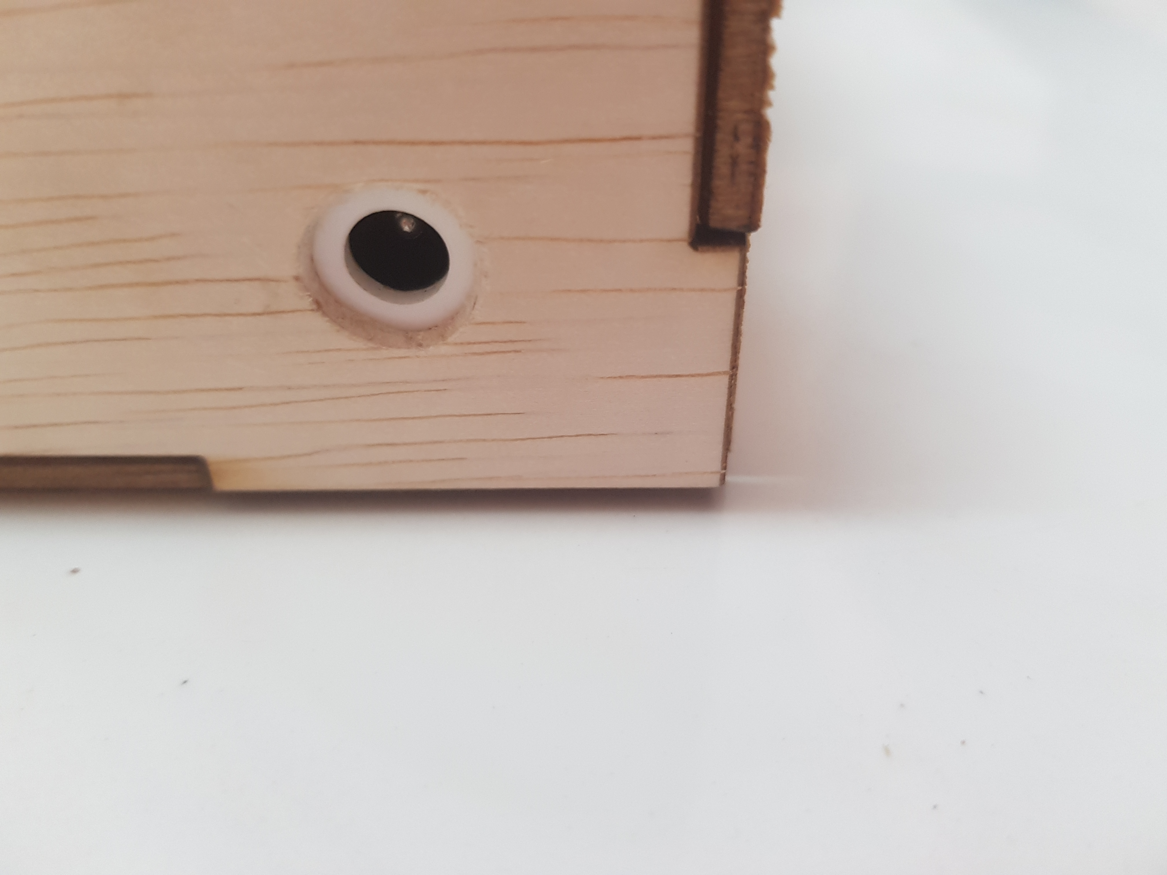
When I decided to change my power source to an external power source, I also had to drill a hole that would fit the plug/cable. However, the slot in the barrel jack plug that I had wasn't really centered, and it didn't really look that nice, so for aesthetic purposes, I decided to put it on the inside of the outer body instead. However since the wall was 3mm thick, if I put it on the inside of the outer body, it would have prevented the plug from plugging all the way in. So I quickly designed a piece that would go into the hole in the outer wall and would be 2mm thick.
I also soldered everything that needed to be soldered together. I used 'male' wires and soldered one end to wherever they needed to be, and plugged the pin end into my breadboard. Soldering was terrible. I've never soldered before, so I kind of just winged it after a brief introduction from a helpful senior. Things that stick kept getting unstuck, and things that weren't supposed to stick kept getting stuck. But I eventually finished soldering (somewhat).
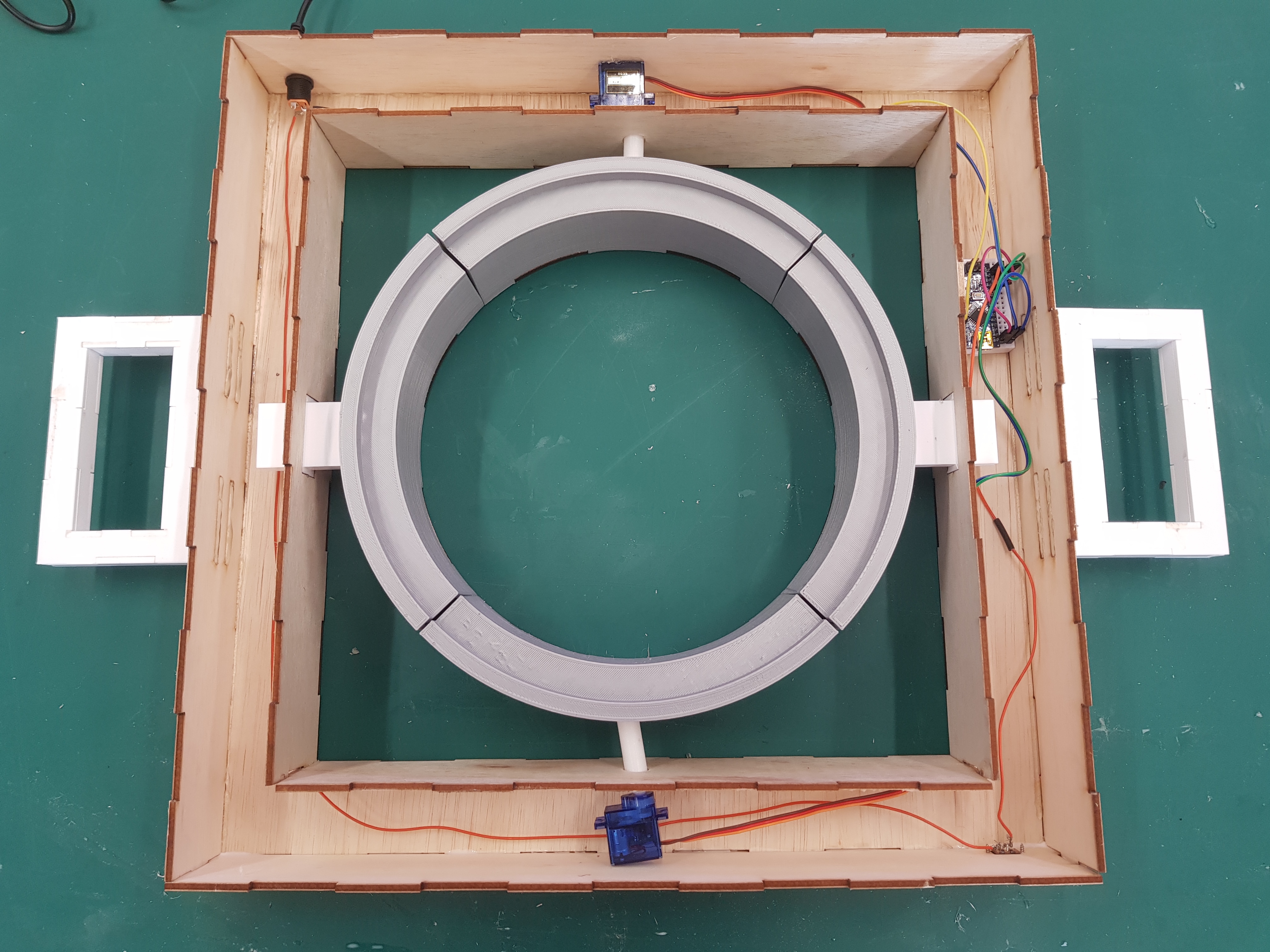
So after lots of resoldering and also possibly minor burns, my automatic flour sifter is complete! Much to my disappointment, it doesn't work because the gear connecting to the gear rack had a bit of wiggle room, which meant that it couldn't shift the centre piece very well. It might also be a problem with the torque force, because the servo motors simply might not have enough power to shift the centre piece. My lecturer suggested for me to put a couple supports for the gear connector and attach them using bearings, so the gears can still rotate but they'd be more secure and won't be able to move with the supports. Unfortunately, I didn't have the time or the technical skkill to put that in place, so until I do, my automatic flour sifter will just have to remain as it is.
Even though it doesn't work as intended, I'm still pretty happy with it because theoretically it would work. And through the course of making it, I'd learned a lot and I think this is still a pretty good start to my first big project. Also, it's beautiful. Thank you to everyone who have helped me with this project, and hopefully, I'll be able to make it work someday soon.